To launch auto-scaling for Virtual IPS Sensors from Azure, perform the following steps:
Task
-
Click
All services and then
Virtual machine scale set under
COMPUTE section.
The Virtual machine scale set blade opens.
-
Click
+ Add.
The Create a virtual machine scale set window opens with the Basics tab.
-
On the
Basics tab, enter the following details:
Option Definition Project details Subscription - The subscription linked with your Azure account is selected by default. If you have multiple subscription accounts, select the subscription account in which you would like to launch the Virtual IPS Sensor scale set.
Resource group
- Create new - You can create a new resource group to be protected.
- Select existing - Select the resource group to be protected.
Scale set details Virtual machine scale ser name - Type a name for the Virtual IPS Sensor scale set.
Region - Select the region where the Virtual IPS Sensor must be created.
Availability zone - [Optional] Select the availability zone for providing high availability to the Virtual IPS Sensor.
Instance details Image - Select the Virtual IPS Sensor image to be deployed as a virtual machine scale set.
Size - Select the size of the Virtual IPS Sensor VM.
Administrator account Authentication type - Select SSH authentication type.
Note
Only SSH Public Key authentication type is supported for Sensors.
Username - Enter the user name that must be used for Virtual IPS Sensor virtual machine.
SSH public key store - Select the Use existing public key option.
Note
The private key file for the SSH public key must be in .pem format.
Note
The Virtual IPS Sensor cannot validate the SSH key pair generated in the Azure portal.
Note
Azure validates the information you enter and a green tick appears against the fields where you enter details.
-
Click
Next: Disks >.
The Disks tab opens. Enter the following details:
Option Definition Disk options OS disk type - The Premium SSD type is selected by default. Trellix recommends you use Premium SSD disk type for Virtual IPS Sensors for improved performance.
Data disks You can attach a new disk or an existing disk for your virtual machine. Advanced Use managed disks - Select Yes for Azure to manage the disk availability automatically.
-
Click
Next: Networking >.
The Networking tab opens. Enter the following details:
Option Definition Virtual network Select the virtual network in which the Controller must be deployed. Network interafce Create new nic - You can create a new network interface for the vIPS Controller virtual machine. Or,
Select existing new network interface for the vIPS Controller virtual machine.
-
Click
Next: Scaling >.
The Scaling tab opens. Enter the following details:
Option Definition Instance Intial Instance Count — Enter the number of active instance available in the virtual machine scale set at a time. For External Controller high availability, Trellix recommends you to set this value to 1.
Scaling Scaling policy — Trellix recommends you to select this option to scale the Sensor set based on any capacity or schedule. Minimum number of VMs — Enter the minimum number of Sensors to be available in the scale set.
Maximum number of VMs — Enter the maximum number of Sensors to be available in the scale set.
Scale out CPU threshold (%) — Enter the CPU percentage threshold to start the Scale out for autoscale set.
Duration in minutes — Enter the duration for which the samples are collected for the metric when auto scaling.
Number of VMs to increase by — Enter the number of Sensors to be deployed newly when the autoscale reaches Scale out condition.
Scale in CPU threshold (%) — Enter the CPU percentage threshold to start the Scale in for autoscale set.
Number of VMs to decrease by — Enter the number of Sensors to be deleted when the autoscale reaches Scale in condition.
-
Click
Next: Management >.
The Management tab opens. Enter the following details:
Option Definition Upgrade policy Upgrade mode — Select the Manual - Existing instance must be manually upgraded upgrade mode.
-
Click
Next: Health >.
The Health tab opens. Enter the following details:
Option Definition Health Monitor application health — Select Disable option for monitoring the health status. -
Click
Next: Advanced >.
The Advanced tab opens. Enter the following details:
Option Definition Custom Data Enter the Custom Data for the Virtual IPS Sensor in the following format: { "Primary Manager IP" : "IPS_PRIMARY_MANAGER_PRIVATE_IP", "Secondary Manager IP" : "IPS_SECONDARY_MANAGER_PRIVATE_IP", "Cluster Name" : "CLUSTER_NAME", "Sensor Shared Key" : "SHARED_KEY" }Custom data parameters Parameters Description Primary Manager IP Private IP address of the primary Manager Secondary Manager IP Private IP address of the secondary Manager Cluster Name Name of the Cluster in the Manager Sensor Shared Key Shared secret key to establish trust with the Sensor -
Click
Next: Tags >.
The Tags tab opens. On this tab, you can categorize resources by applying a tag name and value to multiple resources and resource groups.
-
Click
Next: Review + create >.
The Review + create tab opens. Validate the summary details which contain all the parameters selected. Make sure the validation is passed.
-
Click
Create.
The Virtual IPS Sensor virtual machine is created.
Tip
To view the Virtual IPS Sensor virtual machine, go to All services, under the Compute section, and click Virtual machines. You are directed to the Virtual machines page where you can view or delete the Virtual IPS Sensor virtual machine.
-
After the Virtual IPS Sensor is deployed, go to
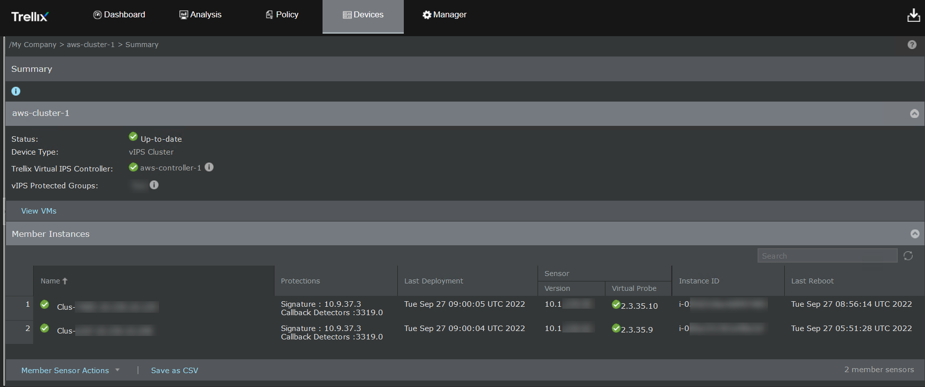
Devices → <Admin Domain Name> → Devices → <Device Name> → Summary page in the Manager to validate successful deployment of the Virtual IPS Sensor.
If the Virtual IPS Sensor is deployed successfully, a green icon appears next to the Virtual IPS Sensor name.