The NS7x50 front and rear panel details are described below.
The NS7150/NS7250/NS7350 Sensor model

Console port (1)
RJ-11 port (1) for passive fail-open control of two built-in SFP+ ports in slot G0. The RJ-11 port supports 1 Gbps (SFP) copper or fiber and 10 Gbps (SFP+) (SR and LR).
SFP+ 1/10 Gigabit Ethernet ports (2)
Important
The RJ-11 port controls only the G0 SFP+ 1/10 port pair in passive fail-open mode.
Two slots for I/O modules (Any combination of the interface modules can be used)
Note
The supported interface modules need to be purchased separately.
RJ-45 10/100/1000 Mbps with internal fail-open Ethernet Monitoring ports (6)
RJ-45 10 Gbps/1 Gbps/100 Mbps with internal fail-open Network Interface Module (4)
SFP/SFP+ 1/10 GigE Monitoring ports (8)
SFP/SFP+ 10/1 GigE SM 8.5 micron with internal fail-open Monitoring ports (4)
SFP/SFP+ 10/1 GigE MM 50 micron with internal fail-open Monitoring ports (4)
SFP/SFP+ 10/1 GigE MM 62.5 micron with internal fail-open Monitoring ports (4)
RJ-45 10/100/1000 Mbps Ethernet Monitoring ports (8)
The supported transceiver modules are SFP+ Fiber (MM and SM), SFP Fiber (MM and SM) and SFP Copper.

Power supply inlet (2)
USB ports (2)
RJ-45 10 Gbps/1 Gbps Management port (Mgmt) (1)
RJ-45 10 Gbps/1 Gbps Response port (R1) (1)
The NS7x50 Sensors have five fan units on the top.
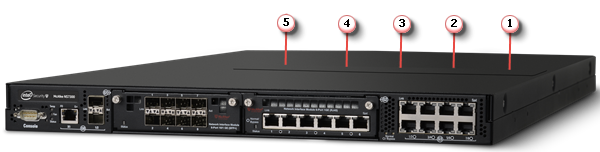
The direction of airflow in all the Sensors is front to back. Cold air enters through the front of the chassis.
Note
The fan units and power supplies are field replaceable.
The following table gives the details of the supported ports.
Ports | NS7150/NS7250/NS7350 |
|---|---|
Fixed Gigabit Ethernet—Copper ports (internal fail-open) | 8 |
Fixed 10 GigE/1 GigE (SFP+) ports | 2 |
Network I/O slots | 2 |
Network I/O modules | 4-port 10/1 GigE SM 8.5 micron with internal fail-open 4-port 10/1 GigE MM 50 micron with internal fail-open 4-port 10/1 GigE MM 62.5 micron with internal fail-open 4-port RJ-45 10 GigE with internal fail-open 6-port RJ-45 1 GigE with internal fail-open 8-port (SFP+/SFP) 10/1 GigE |
10 Gigabit Ethernet | Modular up to 18 |
Dedicated Response ports (RJ-45) | 1 (10G/1G) |
Dedicated Management ports (RJ-45) | 1 (10G/1G) |
USB ports | 2 |
Console port — Use to set up and configure the Sensor using the CLI.
RJ-11 port — Controls the SFP+ 1/10 Gigabit Ethernet port pair in passive fail-open mode
SFP/SFP+ 1/10 Gigabit Ethernet ports — Enables to monitor two SPAN ports, two segments in-line, or a combination
RJ-45 10/100/1000 Mbps Ethernet Monitoring ports — Enables to monitor eight SPAN ports, four segments in-line, or a combination
External USB ports — Use these in troubleshooting situations for system recovery purposes. You need to restart the Sensor through the USB storage device.
RJ-45 10G/1G Management port— Use for communication with the Manager server. You can assign an IP address to this port during installation.
RJ-45 10G/1G Response port — When you're operating in SPAN or tap mode, it enables you to inject response packets back through a switch or router.
Power Supply — Power supply is included with an NS7x50 Sensor. The supply uses a standard IEC port (IEC320-C13). Trellix provides a standard, 2m NEMA 5-15P (US) power cable (3 wire). International customers must procure a country-appropriate power cable.
The NS-series Sensor does not have internal taps; you must use it with a third-party external tap to run it in tapped mode.