You can view or configure settings for the 1 Gbps monitoring ports.
Task
- Navigate to Devices → <Admin Domain Name> → Devices → <Device_Name> → Setup → Physical Ports.
-
Double-click on the row of the monitoring port that displays the Connector Type as
SFP. The
Monitoring Port Details window is displayed.
View Monitoring Port window 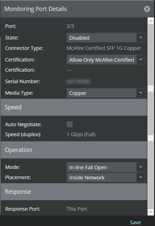
- Select the Auto Negotiate checkbox if the speed of the port has to match with the rest of the network.
-
Select the
Speed of the port. Port speed details the speed of traffic being monitored. You can set the port speed by selecting from the following values on the drop-down list:
- 1 Gbps (full)
- 100 Mbps (full)
- 100 Mbps (half)
- 10 Mbps (full)
- 10 Mbps (half)
The LED link will turn green if the speed is set to 10 Mbps or 100 Mbps. - Specify whether a Trellix Certified SFP type should be used.
-
Select the
State as either
Enabled (on) or
Disabled (off). The
Link displays
Up (on) or
Down (off) accordingly.
Note
If your Link displays as Down and your State is Enabled, there may be a problem. Check the system faults on the Faults tab in Logs page for more information.
-
Select an
Mode from the following:
Caution
Your device cabling must match the selected operating mode for correct system functionality. Improper deployment may result in system faults, including missed attacks and system failure.
- Inline Fail Open - Active
- Inline Fail Open - Passive
-
Inline Fail Closed
Note
Inline fail-open and Inline fail-closed are determined by how the port cables are connected. Fail-open operation for GE ports requires use of the optional Bypass Switch provided in the Gigabit Optical Fail-Open Bypass Kit (sold separately). You should not select the Inline Fail Open option if the optional external Bypass Switch is not present.
- SPAN or Hub
-
Tap
For FE ports configured in Tap mode, select External if using an external tap, or Internal if using the internal tap feature. GE ports can only be configured for External Tap mode.
Caution
If FE ports fail when configured in Internal Tap Mode, traffic will continue to pass. However, your device will experience some latency that may block traffic upto a minute before the passthru is established.
If a port is functioning as part of a Port Pair, the Peer Port is listed. For example, if port 1A is configured for Tap mode, port 1B is listed as the Peer Port. All ports are wire-matched internally with a single peer, for example 1A-1B make up a port pair. However, 1A-2B cannot be a port pair. - Select Placement of your network where the current port is connected: Inside Network or Outside Network. This step applies to Tap or Inline modes only.
-
Wherever applicable, select a
Response Port. The following choices are available:
- This Port: Respond out of the detection port to the segment. This is selected by default for Inline and SPAN operating modes.
- R1: Sends responses through a R1 port
- R2: Sends responses through a R2 port
Tip
You can assign a response port to more than one device monitoring port. However, knowing where your response ports are connected in the network will make for the best response system.
- Click Save to save changes.