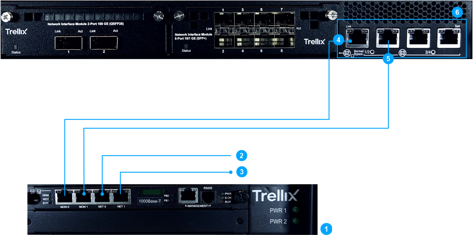
Callout | Description |
|---|---|
1 | 10/100/1000 Copper fail-open switch module |
2 | Connection to a network device (inside) |
3 | Connection to a network device (outside) |
4 | Sensor monitoring port G3/1 (inside) |
5 | Sensor monitoring port G3/2 (outside) |
6 | Sensor monitoring ports on an NS9500 Sensor. |
The steps below provide steps for connections for both copper and fiber fail-open switches.
Steps:
Plug the inside network cable connector into the Cat 5/Cat 5e/LC port, labeled Net 0 on the fail-open switch.
Plug the other end of this cable to the corresponding network device.
Plug the outside network cable connector into the Cat 5/Cat 5e/LC port, labeled Net 1 on the fail-open switch.
Plug the other end of this cable to the corresponding network device.
Result: The fail-open switch is now connected to network devices for the inside network and outside network. Your next step is to connect the fail-open switch to the Sensor.