Prerequisites:
If you require external access to VMs connected to this switch, you will be required to connect an additional physical NIC on the ESX to a physical switch.
You connect monitoring ports to standard vSwitches. When you create a standard vSwitch, ESX creates a default port group for this vSwitch. Each monitoring port in a Virtual Sensor must be connected to different port groups.
Steps:
Optionally, connect an additional physical NIC on the ESX to the adjacent physical switch.
In scenario 4, for example, you must connect an additional NIC to the corresponding physical switch.
Log on to the ESX as the root user in VMware vSphere Web Client.
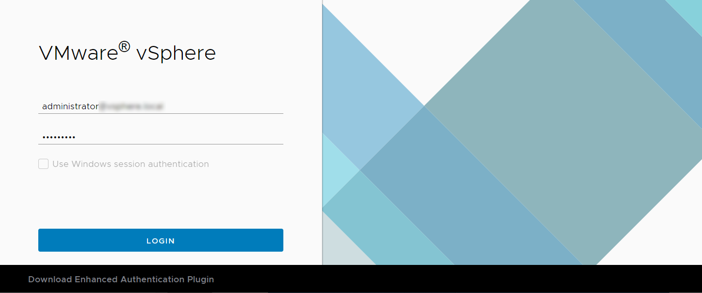
Select the required ESX server and select Configure → Networking → Virtual switches.
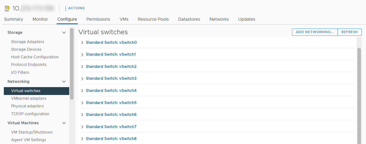
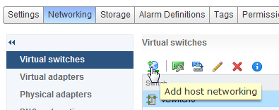
Click the ADD NETWORKING tab.
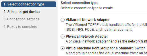
In the Select connection type section, select the required connection type and click NEXT.
Selecting the connection type depends on your network design and requirements. If the VMs that will be connected to this switch do not need access outside the ESX, you might select Virtual Machine Port Group for a Standard Switch. However, for requirements as in scenario 4, it is mandatory to select Physical Network Adapter. Consider that you now select Virtual Machine Port Group for a Standard Switch.
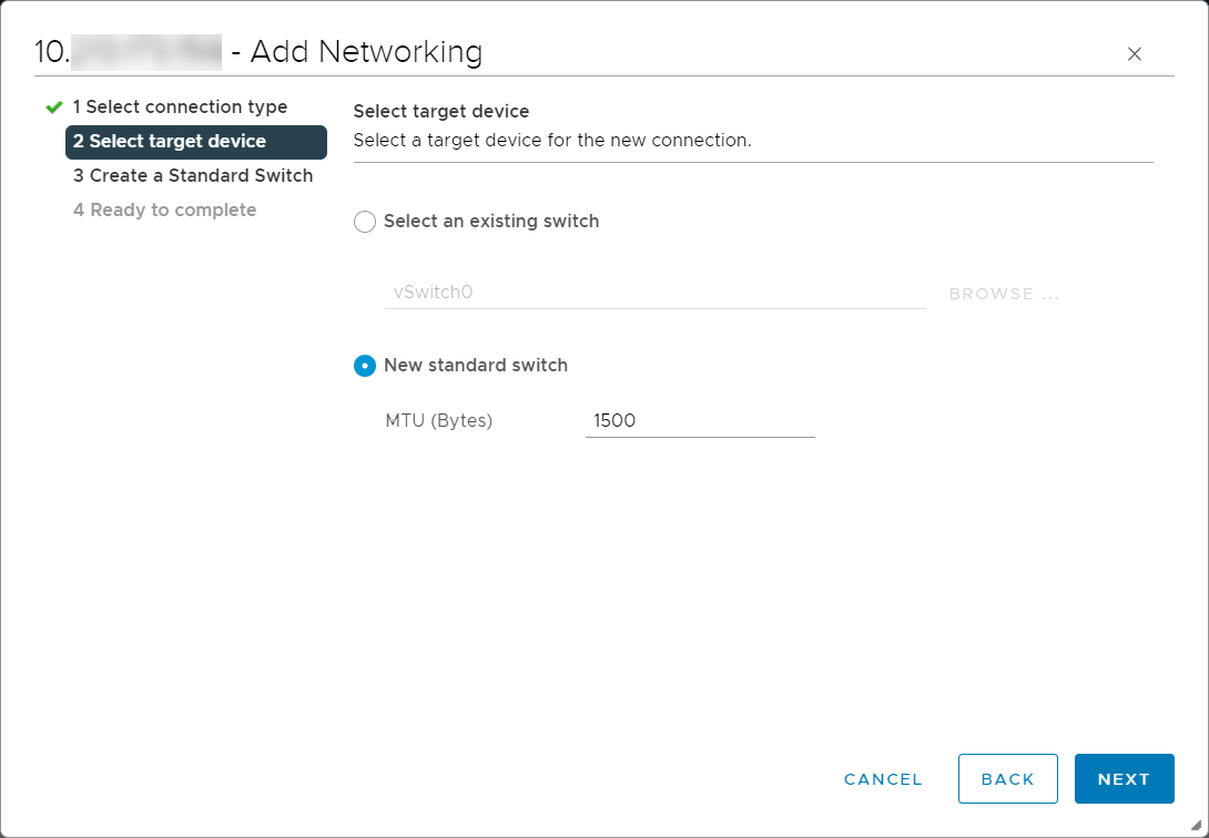
In the Select target device section, select New standard switch and set the value of MTU (Bytes) (here, 1500). Click NEXT.
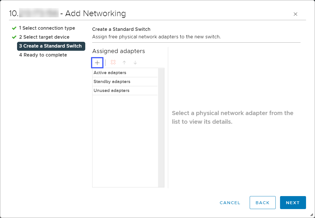
Based on your network requirements, click on the Add adapters (+) icon and select the corresponding physical network adapter. Then click NEXT.
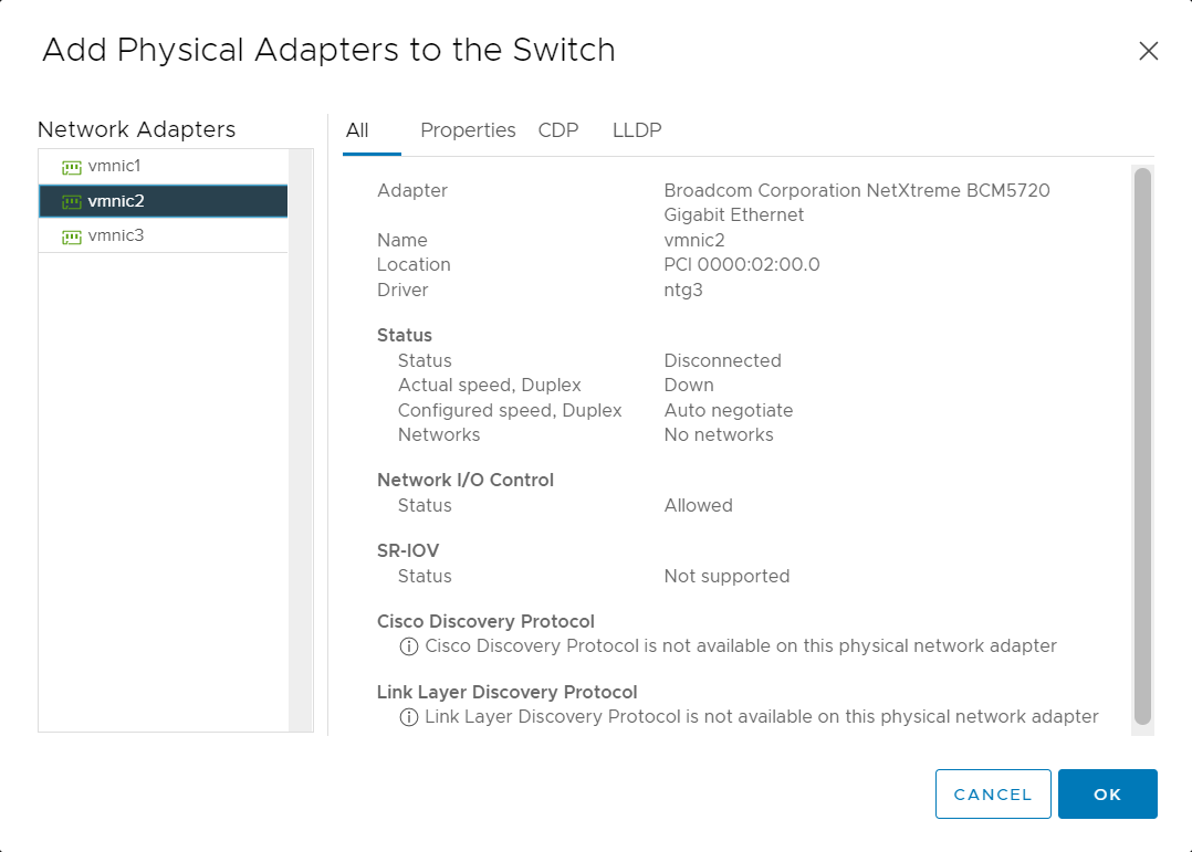
If you select an adapter, make sure that a physical NIC corresponding to the network adapter you selected is connected to the network.
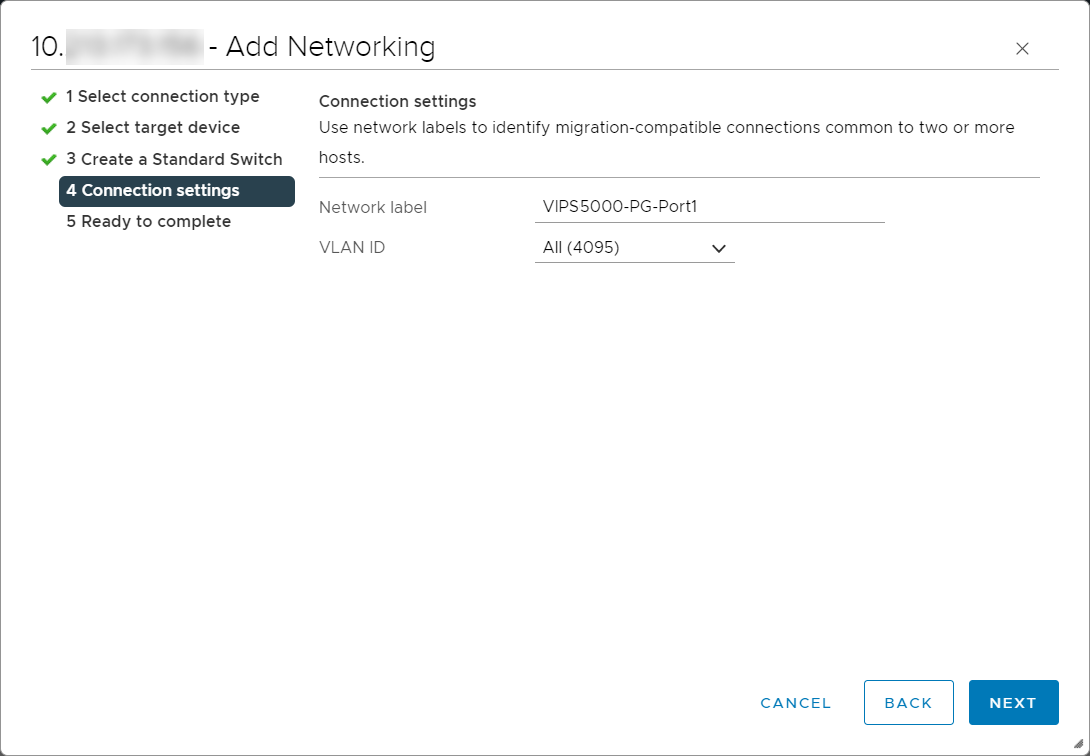
In the Network Label field, enter the required name for the default port group that the wizard creates for the switch.
You can modify Network Label even later. For example, you can name it as VIPS5000-PG-Port1 for easier management.
In the VLAN ID drop-down, select All (4095) and click NEXT.
Click FINISH.
This port group is now listed under the Virtual Switch.
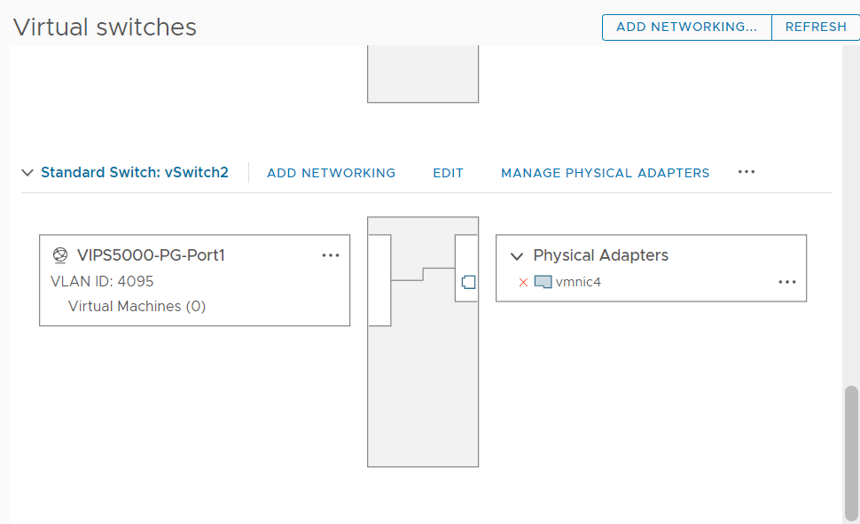
Navigate to Configure → Networking → Physical adapters and verify if Configured Speed of the assigned physical adapter is set to Auto negotiate.
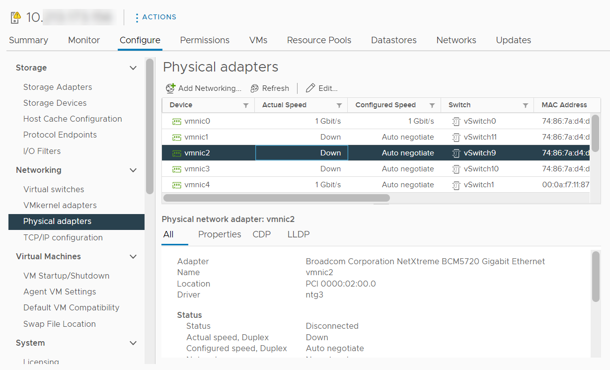
For other property values, you can leave them with the default values.
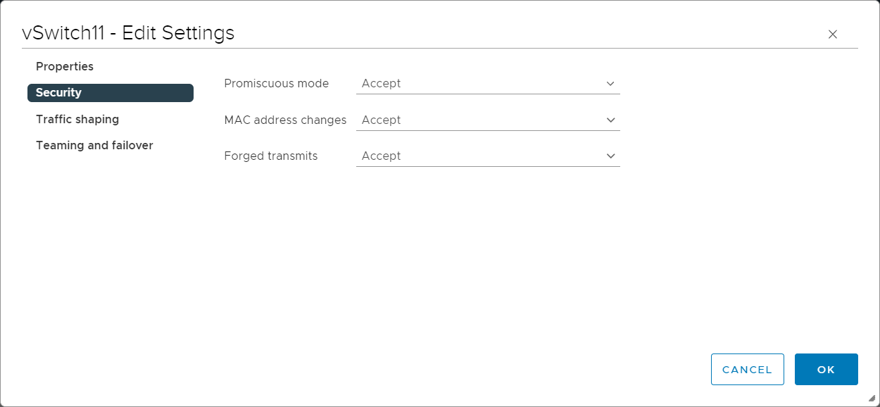
Modify the security properties of the vSwitch.
Scroll down to the newly created switch, and click the EDIT tab.
Go to Security section, make sure the fields are set to the values mentioned below, and then click OK.
Promiscuous mode — Accept
MAC Address Changes — Accept
Forged Transmits — Accept
Note
Select the Override check-box to be able to change the state of an option.
Modify the security settings of the default port group.
It is assumed that you will use this port group to connect the monitoring port of a Sensor.
Under the newly created switch, click on the ellipsis icon next to the switch port group that you created and click Edit Settngs.
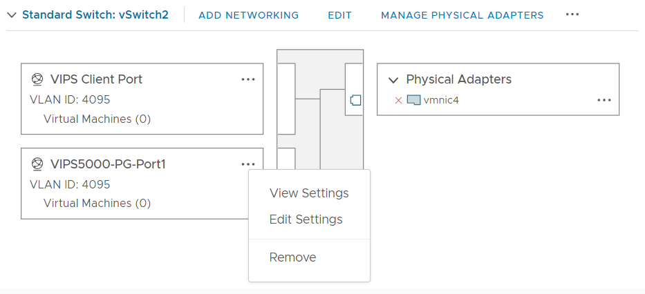
In the Properties section, modify the Network label, if required.
Make sure VLAN ID is set to All (4095).
This switch port group must receive all VLAN traffic similar to a trunk port.
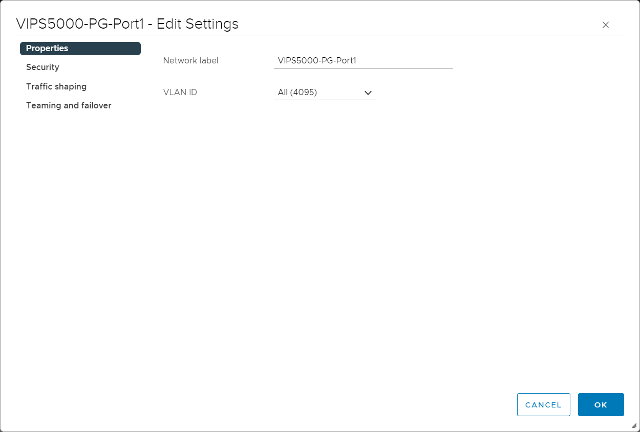
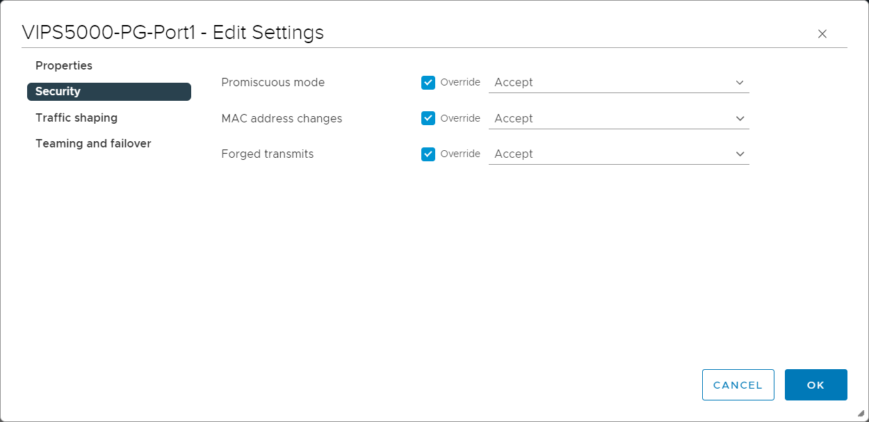
Go to the Security section, make sure the fields are set with the following values and click OK.
Promiscuous mode — Accept
MAC Address Changes — Accept
Forged Transmits — Accept
Note
Select the Override check-box to be able to change the state of an option.
This is mandatory for the port group that you will use for any Sensor monitoring port.
Create a new port group for the other VMs in this vSwitch.
For example, in scenario 2, this is the port group that you will use for the 10.10.10.16 server.
Note
Skip this step for scenario 4.
Expand the corresponding vSwitch node and click the ADD NETWORKING tab.
The Add Networking wizard appears.
In the Select connection type section, select Virtual Machine Port Group for a Standard Switch and click NEXT.
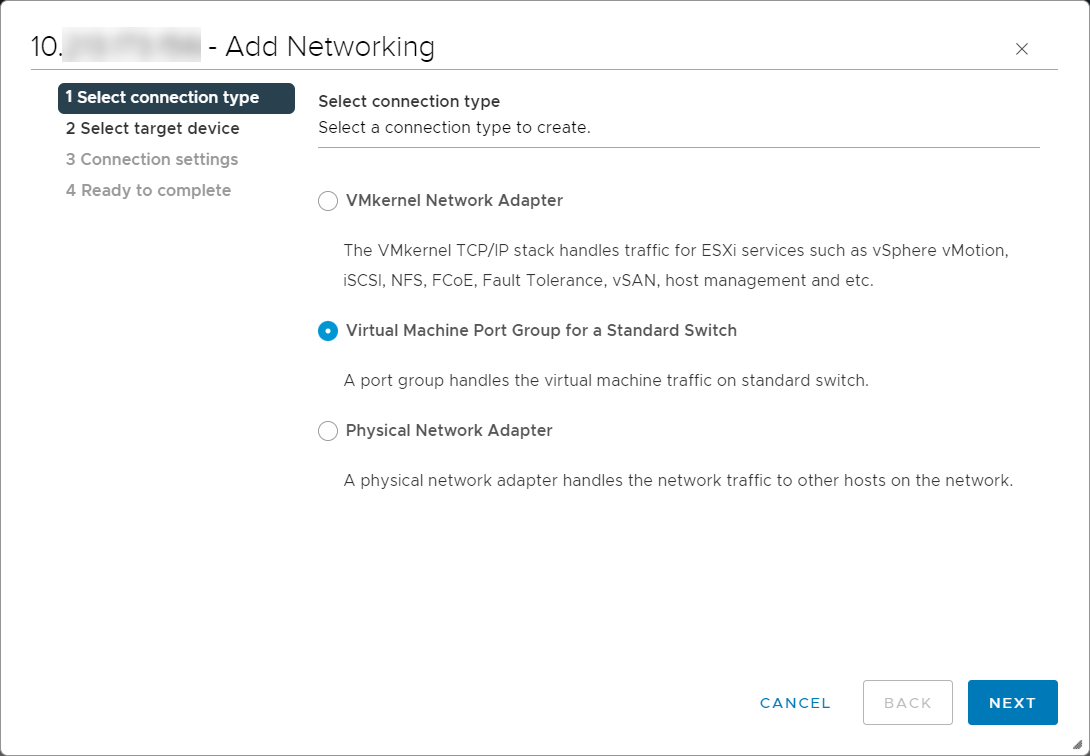
In the Select target device section, select Select an existing standard switch and make sure the vSwitch that you created is selected. Then click NEXT.
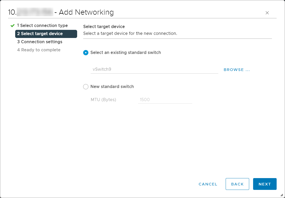
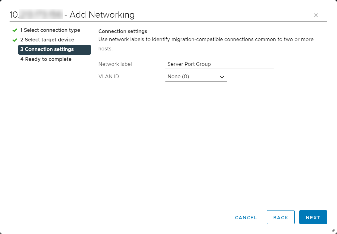
In the Connection settings section, enter the required name in the Network Label field for the default port group that the wizard creates for the switch. For example, you can name it as Server Port Group for easier management.
You may modify Network Label later.
In the VLAN ID (Optional) field, you can specify the required VLAN. For scenario 1, for example, select None (0) and click Next and then, click FINISH.
None (0) means that the traffic is not tagged with a VLAN.
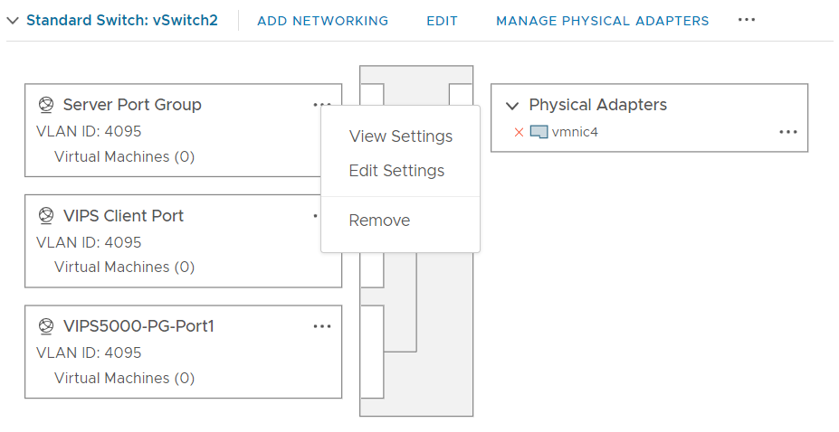
Under the respective switch node, click the ellipsis icon next to the switch port group (Server Port Group) that you created and select Edit Settngs.
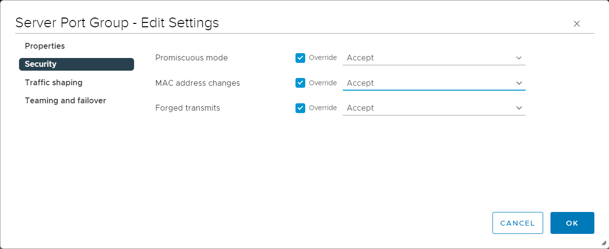
Go to the Security section, make sure the fields are set with the following values and click OK.
Promiscuous mode — Accept
MAC Address Changes — Accept
Forged Transmits — Accept
Note
Select the Override check-box to be able to change the state of an option.
Click OK to close the Edit settings wizard.