Front panel
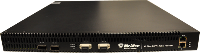
Ethernet management port (1)
RJ Connector (1)
Link and Activity LEDs for power
40G network ports (2)
Activity LEDs for network ports
Inline LED
40G appliance ports, with hot swappable QSFP+ modules (2)
Link and Activity LEDs for appliance ports
The table below describes the behavior of the LED color to the speed at which the data ports detected the QSFP+ modules or established a link.
Speed | Color | Activity | Link | Port Type |
|---|---|---|---|---|
40G | Red | N/A | Solid | Appliance |
Rear panel
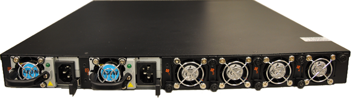
Power supply 1
Power supply 2
Fan units (4)
The Bypass Switch provides two redundant power supply inputs to minimize the chance of power loss or failure.
In addition, the Bypass Switch continuously monitors the power supply voltage to detect any instance of power decline or outage. If a power failure is detected, Power Fail Protection Operation is triggered, which initiates a switch to Bypass Mode. During this no power state, the N1 and N2 ports will physically connect to create a passive bypass path without any traffic interruption between port N1 and port N2.