This section covers the steps for installing and configuring OVS with DPDK on a host machine with CentOS. These steps are required to attain maximum performance on vIPS Sensors deployed in KVM. This section covers configuration using OVS version 2.12.0 and DPDK version 18.11.2. Users may choose to configure the latest versions. However, steps might vary during OVS with DPDK configuration.
Prerequisite:
Make sure that you have enabled Virtualization in BIOS.
Steps:
Install OVS with DPDK on CentOS
Open a terminal in CentOS and execute the following commands to install OVS with DPDK:
sudo yum install -y epel-release centos-release-openstack-train sudo yum install openvswitch libibverbs sudo yum install dpdk-tools
Enable and start the OVS service
Upon completing the installation, enable and start the OVS service by executing the following commands:
systemctl enable openvswitch systemctl start openvswitch
Enable Input-Output Memory Management Unit (IOMMU) or passthrough
The IOMMU kernel parameter is enabled by editing the Grub config file - /etc/default/grub using a text editor. Scroll down to the line starting with
GRUB_CMDLINE_LINUXand add the parameterintel_iommu=on iommu=ptat the end of the code.A sample of the updated code can be seen below:
GRUB_CMDLINE_LINUX="crashkernel=auto spectre_v2=retpoline rd.lvm.lv= centos/root rd.lvm.lv=centos/swap rhgb quiet intel_iommu=on iommu=pt”
Upon saving the file changes, execute the command
grub2-mkconfig -o /etc/grub2-efi.cfgin case the boot mode configured on your system is Unified Extensible Firmware Interface (UEFI), andgrub2-mkconfig -o /boot/grub2/grub.cfgin case the boot mode configured on your system is Legacy/Basic Input Output System (BIOS).Upon executing the command, reboot the machine for the changes to apply.
Create HugePages
Note
It is recommended to have 16GB of available hugepages on the machine if you are deploying IPS-VM5000, and 8GB of available hugepages on the machine if you are deploying IPS-VM600. The hugepages can be assigned at bootup by editing
GRUB_CMDLINE_LINUXin the Grub config file.To set the machine to have 16GB of hugepages, open the Grub config file - /etc/default/grub using a text editor. Scroll down to the line starting with
GRUB_CMDLINE_LINUXand add the parameterdefault_hugepagesz=1G hugepagesz=1G hugepages=16beforeintel_iommu=on iommu=pt.A sample of the updated code can be seen below:
GRUB_CMDLINE_LINUX="crashkernel=auto spectre_v2=retpoline rd.lvm.lv= centos/root rd.lvm.lv=centos/swap rhgb quiet default_hugepagesz=1G hugepagesz=1G hugepages=16 intel_iommu=on iommu=pt”
Upon setting the hugepage size, mount the hugepages by executing the command
mount -t hugetlbfs none /dev/hugepages.Isolate cores for vIPS Sensor deployment
Note
You need to isolate CPU cores by dedicating them for DPDK to achieve high-performance packet processing. Number of cores to be isolated depends on the vIPS Sensor model. If you are using IPS-VM600, you need to isolate a minimum of 4 cores, while for IPS-VM5000, you need to isolate a minimum of 12 cores.
To configure this, edit /etc/default/grub using a text editor. Scroll down to the line starting with
GRUB_CMDLINE_LINUXand add the parametersisolcpus,nohz_full, andrcu_nocbsat the end of the code.A sample of the updated code can be seen below:
GRUB_CMDLINE_LINUX="crashkernel=auto spectre_v2=retpoline rd.lvm.lv= centos/root rd.lvm.lv=centos/swap rhgb quiet default_hugepagesz=1G hugepagesz=1G hugepages=16 intel_iommu=on iommu=pt isolcpus=2,4,6,8,10,12,14,16,18,20,22,24,26,28, 30,32,34,36,38,40,42 nohz_full=2,4,6,8,10,12,14,16,18,20,22,24,26,28,30,32,34,36,38, 40,42 rcu_nocbs=2,4,6,8,10,12,14,16,18,20,22,24,26,28,30,32,34,36,38,40,42"
Note
For faster communications, it is recommended to reserve cores on the same socket or numa node.
You may execute the command
numactl -Hto list lcores on the socket(s).
Bind network devices to dpdk and grant permissions to access dpdk-devices
Note
Before using any network device in ovs-dpdk to create virtual networks, you need to bind those network devices or ethernet ports to Virtual Function I/O(VFIO)-Peripheral Component Interconnect (PCI) driver.
Load the VFIO-PCI kernel module by executing the command
sudo modprobe vfio-pci.Check the status of all the attached network devices by executing the command
dpdk-devbind --status. From the output, find the device ID to which you bind VFIO-PCI.The device ID is in the form of domain:bus:slot.func, for example,
0000:19:00.0.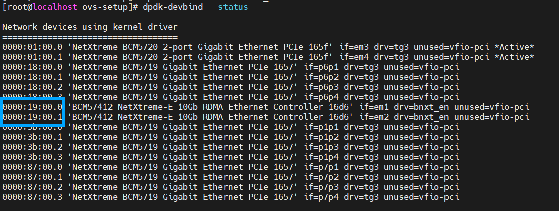
The device IDs are listed in the first column. Pick the device IDs as highlighted in the above image.
Bind the devices to VFIO-PCI by issuing the command
dpdk-devbind --bind=vfio-pci <device_ID1> <device_ID2>.Sample command:
dpdk-devbind --bind=vfio-pci 0000:19:00.0 0000:19:00.1Upon completing this procedure, grant permissions to access the DPDK devices. It is recommended to assign read-write-execute permissions to the vfio directory, and read-write permissions to all the files under the vfio directory. To assign these permissions, execute the following commands:
chmod 0777 /dev/vfio chmod 0666 /dev/vfio/*
Configure ovs-dpdk
You can configure ovs-dpdk using the
ovs-vsctlutility. The parameters to be used in the utility aredpdk-init,dpdk-lcore-mask,dpdk-socket-mem,dpdk-hugepage-dir, andpmd-cpu-mask.Execute the following commands:
ovs-vsctl --no-wait set Open_vSwitch . other_config:dpdk-init=true ovs-vsctl --no-wait set Open_vSwitch . other_config:dpdk-lcore-mask=0x40000000000 ovs-vsctl --no-wait set Open_vSwitch . other_config:dpdk-socket-mem=8192,0 ovs-vsctl --no-wait set Open_vSwitch . other_config:dpdk- hugepage-dir="/dev/hugepages" ovs-vsctl --no-wait set Open_vSwitch . other_config:pmd-cpu-mask=0x15554000000
Note
The parameter
dpdk-lcore-maskis used for the control plane process andpmd-cpu-maskis used for data plane process. In the above command, 0x40000000000 refers to core 42 and 0x15554000000 refers to cores 26,28,30,32,34,36,38,40. The right-most bit 0 in 0x40000000000 and 0x15554000000 refers to core zero. You may set the bitmask values of your choice based on core availability.The dpdk-lcore-mask and pmd-cpu-mask parameters are set with core bitmask. To understand how to set the bitmask value, refer to Using Open vSwitch with DPDK or access the Open vSwitch manual/man pages by executing the command
man ovs-vswitchd.conf.db.For the changes to be applied, restart the OVS service by executing the command
systemctl restart openvswitch.Create virtual networks
To create virtual networks, you need to create bridges (2), add dpdk ports to the bridges, set the device type and device information, set the number of receive side queues, isolate the CPU core for PMD. The aim is to connect the monitoring ports of the Sensor to the ethernet ports connected to dpdk. Refer to the sample commands provided in Step 17 and Step 18 to understand the commands (covering individual parameters) provided below.
To create bridges/virtual switches, execute the commands:
ovs-vsctl add-br <bridge_name1> -- set bridge <bridge_name1> datapath_type=netdev ovs-vsctl add-br <bridge_name2> -- set bridge <bridge_name2> datapath_type=netdev
These bridges connect the dpdk devices to the monitoring ports of the Sensor.
To add dpdk port to a bridge, execute the command
ovs-vsctl add-port <bridge_name1> <dpdk_device_name>.To set the device type and the device information, execute the following commands:
ovs-vsctl set Interface <dpdk_device_name> type=dpdk ovs-vsctl set Interface <dpdk_device_name> options:dpdk- devargs='<domain:bus:slot.func>'
You need to isolate the CPU cores for the PMD that polls a particular rx queue. To perform this, execute the command
ovs-vsctl set Interface <dpdk_device_name> other_config:pmd-rxq-affinity="<queue_number:CPU_core_number,queue_number:CPU_core_number,..."Note
The parameters used in the commands listed under the section Create virtual networks can be combined to form a single command. A sample command combining all the above parameters is shown below:
ovs-vsctl add-port ovsbr1 dpdk1 -- set Interface dpdk1 type=dpdk options:dpdk-devargs='0000:19:00.0' options:n_rxq=2 other_config:pmd-rxq-affinity="0:26,1:28"
Where:
ovsbr1is the name of bridge 1
dpdk1is the name of the dpdk device 1
0000:19:00.0represents <domain:bus:slot.func> belonging to dpdk1
0:26,1:28represent queue 0 is processed by CPU core 26 and queue 1 is processed by CPU core 28Note
The above command is applicable if you are deploying IPS-VM5000 Sensors. In case of IPS-VM600 Sensor deployments, you need to assign only one receiver queue and allocate only one core for affinity. Below is a sample command:
ovs-vsctl add-port ovsbr1 dpdk1 -- set Interface dpdk1 type=dpdk options:dpdk-devargs='0000:19:00.0' options:n_rxq=1 other_config:pmd-rxq-affinity="0:26"
Similarly, follow the above steps to configure bridge 2. A sample command combining all the above parameters is shown below:
ovs-vsctl add-port ovsbr2 dpdk2 -- set Interface dpdk2 type=dpdk options:dpdk- devargs='0000:19:00.1' options:n_rxq=2 other_config:pmd-rxq-affinity="0:30,1:32"
Where:
ovsbr2is the name of bridge 2
dpdk2is the name of the dpdk device 2
0000:19:00.1represents <domain:bus:slot.func> belonging to dpdk2
0:30,1:32represent queue 0 is processed by CPU core 30 and queue 1 is processed by CPU core 32Note
Below is a sample command in case you are planning IPS-VM600 deployment:
ovs-vsctl add-port ovsbr2 dpdk2 -- set Interface dpdk2 type=dpdk options:dpdk-devargs='0000:19:00.1' options:n_rxq=1 other_config:pmd-rxq-affinity="0:30"
Set the queue size for Transmitter (Tx) and Receiver (Rx) queues. Sample commands for setting the queue size:
ovs-vsctl set Interface dpdk1 options:n_rxq_desc=1024 ovs-vsctl set Interface dpdk2 options:n_txq_desc=1024
Add vhostuser ports to the bridges and grant permissions
You can create dpdkvhostuser ports by executing the command
ovs-vsctl add-port <bridge_name1> <vhostuser_name> -- set Interface <vhostuser_name> type=dpdkvhostuser options:n_rxq=2 other_config:pmd-rxq-affinity="<queue_number:CPU_core_number,queue_number:CPU_core_number,..."Following the above syntax, create 2 ports. Below are the sample commands for creating 2 ports:
ovs-vsctl add-port ovsbr1 vhostuser1 -- set Interface vhostuser1 type=dpdkvhostuser options:n_rxq=2 other_config:pmd-rxq-affinity="0:34,1:36" ovs-vsctl add-port ovsbr2 vhostuser2 -- set Interface vhostuser2 type=dpdkvhostuser options:n_rxq=2 other_config:pmd-rxq-affinity="0:38,1:40"
Where:
ovsbr1is the name of bridge 1
ovsbr2is the name of bridge 2
vhostuser1is the vhostuser name 1
vhostuser2is the vhostuser name 2
represents <domain:bus:slot.func> belonging to dpdk2
0:34,1:36represent queue 0 is processed by CPU core 34 and queue 1 is processed by CPU core 36
0:38,1:40represent queue 0 is processed by CPU core 38 and queue 1 is processed by CPU core 40Note
The number of ports you create depends on your usage. If you plan to use all the ports, including the management and response ports, you need to create 8 vhostuser ports. While it is necessary to connect the monitoring ports to the vhostuser ports, the management and response ports can be connected via bridge or vhostuser ports.
Note
Below is a sample command in case you are planning IPS-VM600 deployment:
ovs-vsctl add-port ovsbr1 vhostuser1 -- set Interface vhostuser1 type=dpdkvhostuser options:n_rxq=1 other_config:pmd-rxq-affinity="0:34"
To allow vhostuser ports to be used by VM, grant read-write-execute permissions over the sockets created by OVS service in
/var/run/openvswitch/directory. Sample commands to grant permissions for 2 vhostusers are:chmod 777 /var/run/openvswitch/vhostuser1 chmod 777 /var/run/openvswitch/vhostuser2
Note
If you face any permission issue while starting a Sensor virtual machine, you need to assign read-write-execute permission to the entire openvswitch directory by executing the command
chmod 777 /var/run/openvswitch/*.Note
These sockets are deleted when the OVS service stops and re-created when the service starts. These permissions must be granted again in case the service is stopped and restarted.
Note
If you are restarting the OVS service, you need to add rules/flows to the switches and configure them. Below are sample commands to add new flows:
ovs-ofctl add-flow ovsbr1 in_port=1,action=output:2 ovs-ofctl add-flow ovsbr1 in_port=2,action=output:1 ovs-ofctl add-flow ovsbr2 in_port=1,action=output:2 ovs-ofctl add-flow ovsbr2 in_port=2,action=output:1
Virtual machine configuration file changes
The Sensor virtual machine configuration file is an XML file that stores the configuration information of the machine. Refer to the section Sample XML file to view a sample configuration file.
If you are modifying XML file configuration, make sure you restart the machine by executing the following commands:
virsh destroy <VM_NAME> virsh start <VM_NAME>
where
<VM_NAME>denotes the name of the Sensor virtual machine.