Network scenario for rate limiting HTTP traffic
Consider a network scenario where your internal network is connected to the internet, and Trellix IPS is deployed as shown in the below diagram.
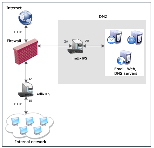
Suppose you want to rate limit the HTTP traffic from the Internet to your internal network, to a specified bandwidth. Your internal network contains some critical servers, to which access from Internet should be limited. So, you want to give less bandwidth to the request traffic coming from the internet to the internal network. But you want to give the response traffic from your internal network to the Internet, a higher bandwidth than the request traffic.
As shown in the diagram, port 1B of the Sensor carries the request traffic from the internet to your internal network. So, port 1B of the Sensor is configured to rate limit the HTTP traffic to a bandwidth of say, 1024 Kbps.
The response traffic from the internal network goes out to the internet through port 1A. As you want to allocate more bandwidth to the response traffic from your internal network, you can configure a rate limiting rule on port 1A of the Sensor; say to a bandwidth of 5120 Kbps.
When the request HTTP traffic passing port 1B exceeds the specified rate limiting of 1024 Kbps, the Sensor rate limits the traffic by dropping excess data packets. Only the configured traffic bandwidth value of 1024 Kbps is allowed to pass through port 1B to the internal network. Similarly, when the response HTTP traffic passing port 1A from the internal network, exceeds the configured rate limiting value of 5120 Kbps, the Sensor rate limits the traffic by dropping excess data packets. Only the configured traffic bandwidth value of 5120 Kbps is allowed to pass through port 1A to the Internet.
Network scenario for DiffServ tagging
Consider a network scenario where the internal network of a University is connected to the internet, and Trellix IPS and the router are deployed as shown in the below diagram.
.png)
Suppose you want to prioritize the HTTP and P2P traffic coming from the University network to the internet. To prioritize the traffic, you can configure the Sensor for DiffServ or VLAN tagging. The role of the Sensor is just to tag the packets and pass it on to an external network device (here router) for DiffServ or VLAN classification.
Suppose you want to give high priority to the HTTP traffic coming from the University network to the internet. You can configure the Sensor port 1B with a DiffServ rule, in which the DiffServ field is set to a value, say 60, for HTTP traffic. When the HTTP traffic from the University network reaches Sensor port 1B, the Sensor tags the packet headers with the DiffServ field value specified in the configuration (60, in this example). The tagged packets are sent to the router, which is configured to do DiffServ categorization. Now the traffic is prioritized according to the DiffServ priority defined in the router. Note that the Sensor only tags the incoming traffic and passes it on to the external network device (in this case, it is the router) which further performs the DiffServ classification.
Similarly, to provide low priority to the P2P traffic coming from the University network to the internet, you can configure port 1B of the Sensor with a DiffServ rule, in which the DiffServ field is set to a value, say 5. When the P2P traffic from the University network reaches Sensor port 1B, the Sensor tags the packet headers with the DiffServ field value specified in the configuration (5, in this example). The tagged packets then reach the router which performs DiffServ classification and prioritization, based on the rules configured in the router.