Trellix vIPS for AWS is a probe-based solution that is capable of inspecting traffic flowing into and out of protected AWS instances. The solution has been designed to adapt to a public cloud environment and to scale with the requirements of your organization's network.
Deployment of Trellix vIPS can be fulfilled to suit your requirements based on the direction of traffic and inspection mode. In this section, we provide you with some scenarios which can serve as basic guidelines in your deployment.
Consider a scenario where Trellix vIPS is deployed to protect an organization's assets in the AWS environment. We assume that some of these assets to be protected are web servers with public IP addresses, and that you have performed the following steps as part of the deployment:
The Trellix IPS Manager:
Is installed in the AWS environment
Is able to reach required Clusters in the AWS environment which will be setup
The Controller is installed by Trellix Technical Support and is able to reach the Manager.
The vIPS Connector is configured and the communication between the Manager and the Controller is successful.
A Cluster and the associated VM groups are configured in the Manager.
The vIPS Probes are installed on every machine that has to be secured by Trellix vIPS.
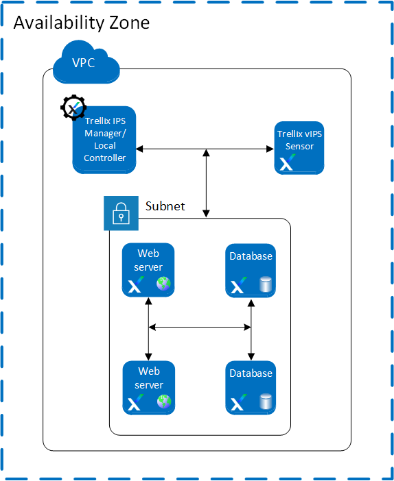
Scenario 1: Deployment of Virtual IPS Sensors with Local Controller
You can deploy the following components:
Trellix IPS Manager
Virtual IPS Sensor
Once the Manager is deployed, select the vIPS Controllers tab from Devices → <Admin Domain Name> → Global → Device Manager. Configure the default Local Controller available on the vIPS Controllers tab.
For steps to configure the controller, see Configure a Controller in the Manager.
Scenario 2: Deployment of Virtual IPS Sensors in IDS Mode
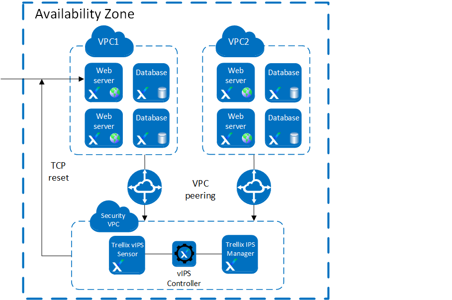
Virtual IPS Sensors detect the attacks in traffic. When the traffic first enters the network, it is directed to the required destination, for example, a web server. This traffic reaches the web server. A copy of the packet is sent to the Virtual IPS Sensor for inspection. If the Sensor detects malicious content in the traffic, it resets the TCP channels which evades the attack. An alert is generated in the Attack Log with the attack details.
Scenario 3: Single Sensor per protected VPC deployment
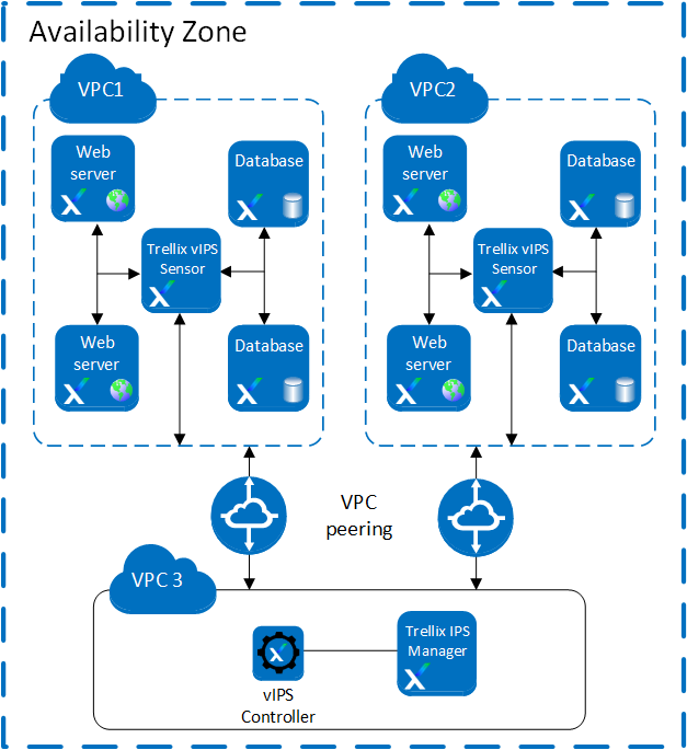
In an environment with a Virtual IPS Sensor Cluster deployed per VPC, traffic load on the individual Virtual IPS Sensor is reduced. The Virtual IPS Sensor is deployed within a VPC where instances must be protected. In such a scenario, the Virtual IPS Sensor inspects traffic from web servers that are present within that VPC. The Manager and the Controller are installed in a separate VPC. This way, traffic is only exchanged with the protected VPC.
Traffic entering the AWS environment is directed to the web server. The virtual Probe installed on the protected web servers intercepts the traffic and routes it to the Virtual IPS Sensors. In case of malicious traffic, an alert is generated in the Manager, and the configured response action is taken. If traffic is non-malicious, it is directed back to the web servers. VPC peering must be enabled between the protected VPC and the VPC that contains the Manager and the Controller.
Note
A single Sensor can handle traffic up to 1 Gbps.
Scenario 4: Multi-zone deployment with auto scaling of Virtual IPS Sensors
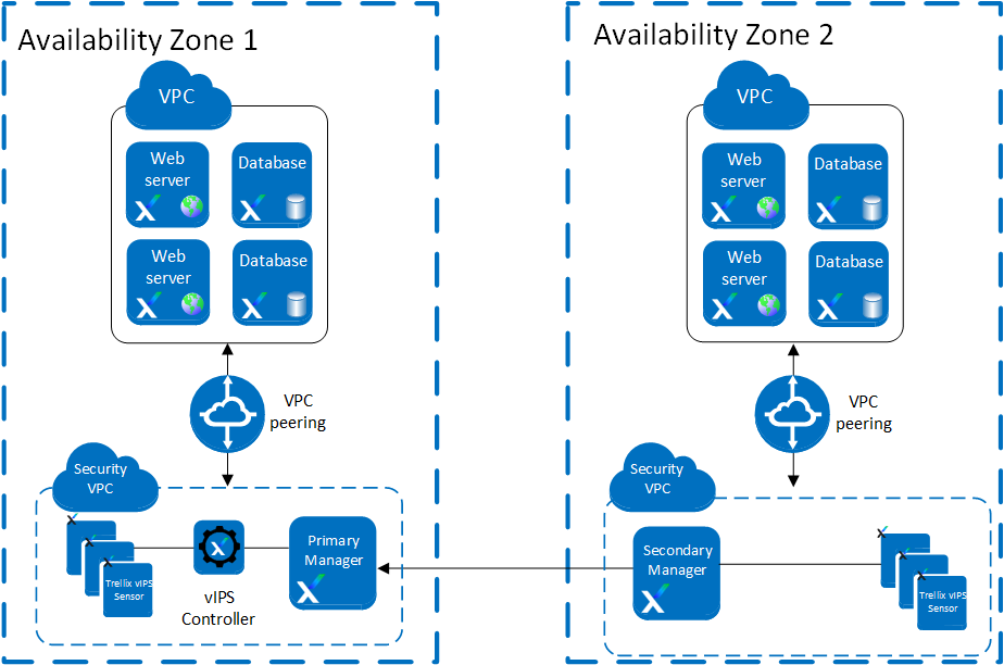
With the Manager Disaster Recovery and Sensor autoscaling features, failover functionality is supported in the network. Failover functionality is possible between two availability zones. You can create two availability zones which are managed by separate Managers that are an MDR pair. When one availability zone fails, the traffic is directed through the other availability zone which has both the Manager and Sensor. Due to this, the traffic flow is not disrupted.
Scenario 5: Securing multiple AWS accounts where the Sensor is in another account with the instances
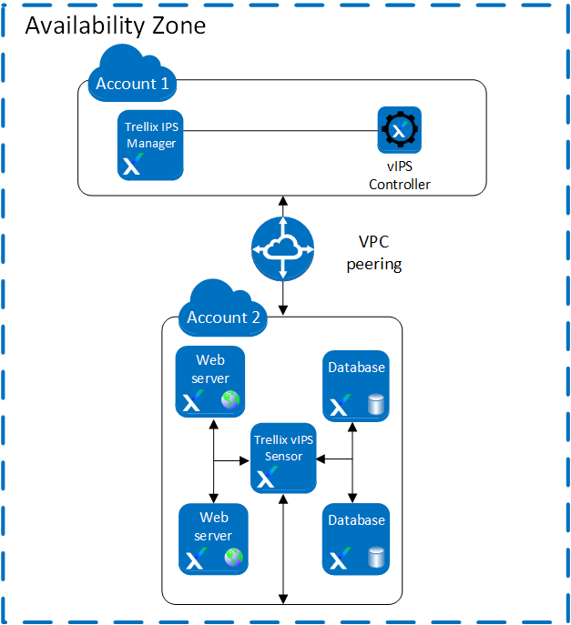
When you want to secure your resources distributed across multiple AWS accounts, you can protect your resources by using Virtual Private Cloud (VPC) peering.
Note
Trellix recommends you to deploy the Sensor in the same Availability Zone or Region as your instances that are to be secured.
You can deploy the following components in one account:
Manager
Controller
You can deploy the following components in other account:
Virtual IPS Sensor
instances
While configuring the Controller you can add the Amazon Resource Names (ARNs) for the second account. Once the Controller is configured, the AWS instances in the second account will also be protected by the Controller.
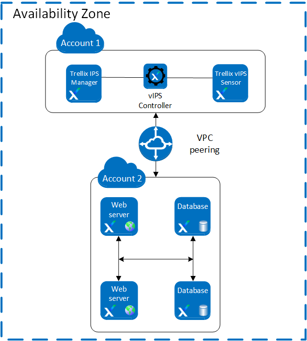
Scenario 6: Securing multiple AWS accounts
When you want to secure your resources distributed across multiple AWS accounts, you can protect your resources by using VPC peering.
You can deploy the following components in one account:
Manager
Controller
Virtual IPS Sensor
Deploy the instances in the second AWS account and connect the accounts using VPC peering.
While configuring the Controller, you can add the Amazon Resource Names (ARNs) for the second account. Once the Controller is configured, the AWS instances in the second account will also be protected by the Controller.