Trellix Intrusion Prevention System Sensors, when deployed in-line, route all incoming traffic through a designated port pair. However, at times, a Sensor might need to be turned off for maintenance or its ports can go down because of an outage. In such a scenario, you might want to continue allowing traffic to pass through without interruption. For such requirements, you can consider an external device called a Fail-Open module. The Fail-Open module can either be an Active Fail-Open module or a Passive Fail-Open module.
Note
In this guide, unless explicitly stated, Trellix Intrusion Prevention System Manager is commonly referred to as "Manager" and Trellix Intrusion Prevention System Sensor is commonly referred to as "Sensor".
An Active Fail-Open module constantly monitors Sensor state. It does this by sending a heartbeat packet through its ports. The heartbeat packet is sent through one of the monitoring ports and received through the other, indicating that the Sensor is functioning normally.
This document describes the contents and how to install and use the Trellix 100 Gigabit Active Fail-Open Bypass Kit (the Kit) for Trellix IPS Sensor NS9500 model with standard 100 Gigabit QSFP28 monitoring ports.
The 100 Gigabit monitoring ports on the IPS Sensor are, by default, fail-closed; thus, if the Sensor is deployed in-line, a hardware failure results in network downtime. Fail-open operation for the monitoring ports requires the use of an optional external Active Fail-Open module provided in the kit.
During normal Sensor in-line fail-open operation, the Active Fail-Open Kit sends a heartbeat packet (every 3 milliseconds by default; user configurable) to the monitoring port pair. If the Active Fail-Open Kit does not receive 3 heartbeat signals (10 milliseconds by default; user configurable) within its programmed interval, the Active Fail-Open kit goes into bypass mode, which removes the Sensor from the traffic path, providing continuous end-to-end data flow but without inspection.
The Active Fail-Open module, by default, is configured to work in the Active/in-line Switching Mode, where the traffic between the public and private networks is routed through the Sensor. Typically, traffic flows from the Public Network to Port NET0 (network in) and will then be actively transferred by the Active Fail-Open module to Port MON0 (appliance in) and routed through the in-line appliance to Port MON1 (appliance out). Active switching will then route the data through Port NET1 and out to the Private Network. This Mode can operate in reverse as well, with traffic routing from a Private to Public Network.
In split TAP mode, the ingress traffic into NET0 is mirrored to MON0 while being passed to NET1. At the same time ingress traffic to NET1 is mirrored to MON1 and passed to NET0. The bidirectional traffic passing from the public network to the private network can be monitored by an appliance with a dual NIC.
When the Sensor fails, the switch automatically shifts to a bypass state; in-line traffic continues to flow through the network link but is no longer routed through the Sensor. In the Bypass Mode, the traffic is routed through a closed loop from port NET0 (network in) to port NET1 (network out) and bypasses the Sensor so that it goes directly from the public network to the private network. This mode can operate in reverse as well, with traffic routing from a private to public Network. Once the Sensor resumes normal operation, the switch returns to the "On" state, enabling in-line monitoring again.
The external active bypass enables plug and play connectivity, includes an auto heartbeat, and does not require additional drivers to be installed on any connected appliance. The Active Fail-Open module has one I/O channel, supports one appliance, and provides the following features:
Secure Web Management Interface (using HTTPS)
CLI access via Serial Console or SSH
Support for SNMP version 1, 2c, 3 (SHA, AES)
The table below shows various models of 100 Gigabit active fail-open switches and the Sensor models that are compatible with these switches.
Fail-open switch | SKU | NS9600 | NS9500 | NS9x00 | NS7600 | NS7500 | NS7x00/NS7x50 |
|---|---|---|---|---|---|---|---|
Active Fiber 100G - QSFP28- SR4 (50μm MTP/MPO) | IAC-2P100FOSR-KIT | Yes | Yes | No | No | No | No |
Active Fiber 100G - QSFP28-LR4 (LC 8.5µm) | IAC-2P100FOLR-KIT | Yes | Yes | No | No | No | No |
Active Fail-Open Chassis: Module based for 100G | IAC-AFOCH100-KT2 | Yes | Yes | No | No | No | No |
Fail-open switch | SKU | NS5x00 | NS3600 | NS3500 | NS3x00 |
|---|---|---|---|---|---|
Active Fiber 100G - QSFP28- SR4 (50μm MTP/MPO) | IAC-2P100FOSR-KIT | No | No | No | No |
Active Fiber 100G - QSFP28-LR4 (LC 8.5µm) | IAC-2P100FOLR-KIT | No | No | No | No |
Active Fail-Open Chassis: Module based for 100G | IAC-AFOCH100-KT2 | No | No | No | No |
You must also make sure you have the requisite QSFP28 when making this choice.
Fiber fail-open switches consist of two types: single mode and multi-mode fibers. The table below gives you some relevant details about both types of fiber optic fail-open switches. This is especially relevant because you must determine the type of fiber that is used your organization network before you decide which type of fail-open switch to use. Also, all product documentation for fail-open kits and decals on the fail-open switches will repeatedly refer to these parameters. The table below shows you the differences between single-mode and multi-mode fiber specifications.
Type | Fiber thickness | Wavelength range |
|---|---|---|
Single mode (Long reach) | 8.5 µm | 1300 nm to 1550 nm |
Multi-mode (Short reach) | 50 µm or 62.5 µm | 850 nm to 1300 nm |
Note
For more details about fail-open kits, refer to the section Fail-Open operation in Sensors in the Trellix Intrusion Prevention System Product Guide. Since this Quick Start Guide will make references to information associated with that chapter, keeping an easily accessible copy of it before you begin installing and configuring your fail-open switch will be helpful.
Hardware description
Front panel
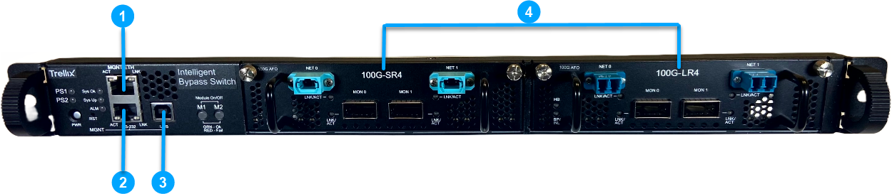
Ethernet management port (1)
RS232 (RJ45) Console Port (1)
USB Port (1)
100G Fail-Open modules Ports with Hot Swappable QSFP28 Transceivers (2)
100G-LR4 (Single Mode)
100G-SR4 (Multi Mode)
LED Section A: chassis LEDs
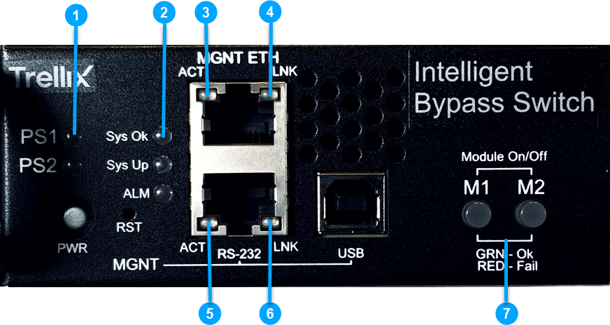
Power LEDs (PS1 and PS2)
Power on: Solid green
Power off: Off
System Status LEDs (Sys Ok, Sys Up, and ALM)
Sys Ok:
System in normal operation condition: Solid green
Identifying a rack: Blinking green
Sys Up:
System initialization during power-up and shutdown: Solid yellow
System fully up: Off
ALM:
System alarm on: Solid red
System alarm off: Off
Management Port Activity
Management Port Link
Console Port (RS232) Activity
Console Port (RS232) Link
Module Power LEDs (M1 and M2)
Module (M1/ M2) is inserted and active: Solid green
Module (M1/ M2) is not inserted: Off
LED Section B: 100G Fail-Open module LEDs
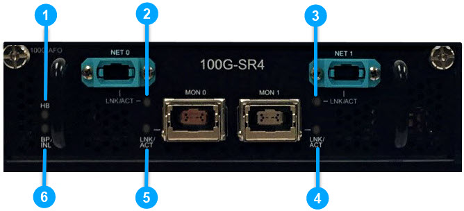
LED | Parameter | Description |
|---|---|---|
1 | Heart beat (HB) | Active Heart beat : Blinking green Inactive Heart beat: Off |
2 3 4 5 | Net 0 (Link/ Activity) Net 1 (Link/ Activity) Mon 1 (Link/ Activity) Mon 0 (Link/ Activity) | Up and no traffic: Solid green Up and with traffic: Blinking green Down: Off |
6 | Bypass/ Inline (BP/INL) | System in Inline mode: Solid green System in Bypass/ TAP mode: Solid yellow |
Bypass Module
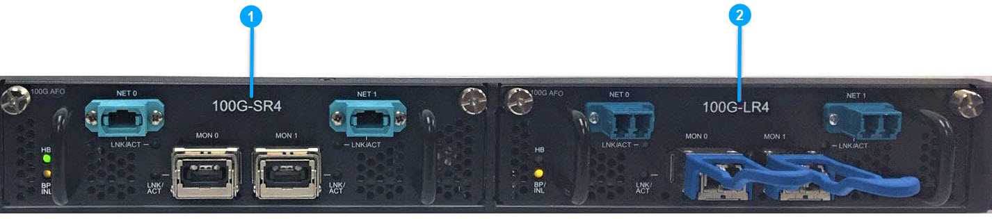
100G-SR4 (Multi Mode)
100G-LR4 (Single Mode)
Rear panel
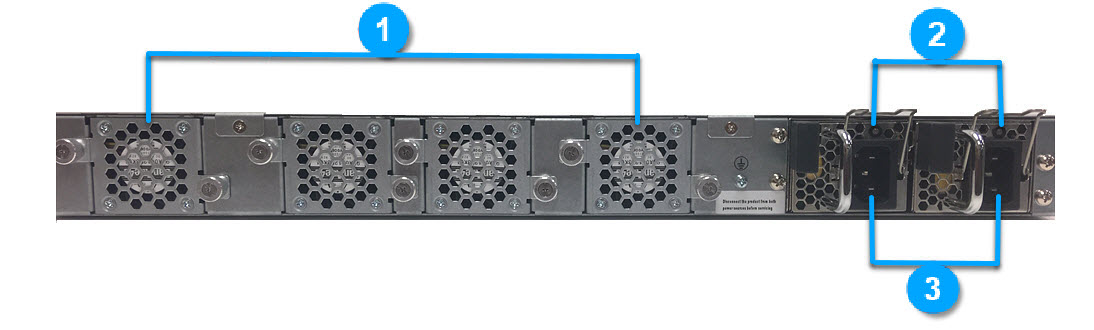
Fan units (4)
LED on the Power Supply Unit
Power switched on - Solid green
Standby - Blinking green
Power fail - Solid red
Internal fan failure (any of the 4 fans) - Blinking red
Power supply 1/2