The following are the high-level steps involved in the configuration and implementation of QoS using Trellix IPS:
- Make sure you have deployed Trellix IPS according to your requirement. See Trellix Intrusion Prevention System Installation Guide for details.
- Make sure you have connected the monitoring ports to the networks that you want to monitor in inline mode. QoS is not applicable to SPAN or tap mode.
- Create the rule objects that you plan to use in your QoS rules. For example, identify the IPv4 and IPv6 addresses and address ranges and create the corresponding rule objects. Similarly, verify if rule objects are available for the applications for which you want to provide QoS.
- If you plan to use the Host DNS Name rule object, make sure you configure the DNS server details in the Manager. Also, make sure these servers are accessible to the Sensor's management port. If the DNS servers are not accessible, a fault message is raised.
Note
The DNS server details apply to Firewall, QoS, integration with GTI for File Reputation, and NTBA.
- If you plan to use user name or user group rule objects, make sure you have integrated the Manager with McAfee Logon Collector 2.0 or later.
- If you are using any time-based rule objects, make sure you have configured the Time Zone in the Manager. Time-based rules are implemented using the local time zone of the corresponding Sensor. The pre-configured Time Zone is GMT.
- For rate limiting, create the Rate Limiting profiles at the admin domain.
- After you create the Rate Limiting profiles, you must assign them to the corresponding inline port pairs.
- You assign the Rate Limiting profiles separately for inbound and outbound directions of a port pair.
- You can assign only one Rate Limiting profile per direction (inbound/outbound) of a port pair.
- You can assign a Rate Limiting profile to any number of port pairs.
- You can assign the same profile to both inbound and outbound directions.
- The Rate Limiting profile type should be equal to or less than the speed of the monitoring port to which you are assigning it.
- Create the required QoS policies at the corresponding admin domain. When you create a QoS policy, you define the QoS rules separately for Rate Limiting, DiffServ tagging, and VLAN 802.1p tagging.
- After you create a QoS policy, you must assign them to the corresponding inline port pairs.
- You assign the QoS policies separately for inbound and outbound directions of a port pair.
- You can assign only one QoS policy per direction (inbound/outbound) of a port pair.
- You can assign a QoS policy to any number of port pairs.
- You can assign the same QoS policy to both inbound and outbound directions.
Assign QoS Policy and Rate Limiting profile to monitoring ports 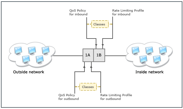
- After you complete assigning the QoS policies to the required Sensor resources, do a configuration update. The Sensor assigns the QoS policy and the Rate Limiting profile to the corresponding Sensor monitoring ports. Consider port pair 1A-1B with a port speed of 1 Gbps in either direction. Assume 1A is connected to the outside network. Then the QoS policy and the Rate Limiting profile that you assigned to 1A-1B/Outbound is assigned to port 1A. The QoS policy and the Rate Limiting profile that you assigned to 1A-1B/Inbound is assigned to port 1B.
Notes and examples
- The important thing to note about QoS is that the policies are applied only to the traffic exiting the port-pair. Consider the example in the previous point. The traffic originating from your inside network is detected at 1B. The Sensor applies the Firewall, Connection Limiting, Recon, Advanced Malware, and IPS policies assigned to port 1B on this traffic but not the QoS policy. The traffic that is allowed to pass through according to these policies reaches 1A and about to egress out through 1A. At this point, the QoS policy assigned to 1A is applied on this traffic. Similarly, the traffic from the outside network enters through 1A and is subjected to the other IPS features. The QoS policy assigned to 1B is applied on this traffic when it exits through 1B.
.png)
- When the Sensor applies a QoS policy, it matches the traffic against the Rate Limiting, Diff Serv, and 802.1p rules simultaneously. That is, it applies the rate limiting rules in a top-down fashion on the traffic. Simultaneously it applies the Diff Serv and 802.1p rules as well in a top-down fashion. When a rule matches the traffic, the Sensor does not consider the remaining rules of the same type.
- Let us use an example to understand how Rate Limiting works:
- Consider port 1B, which is connected to your inside network. Assume that the port speed of 1B is 1 Gbps.
- You create a Rate Limiting profile named Profile_1. This profile is of type 1Gbps. In this, you have allocated 300 Mbps to class 1; 400 Mbps to class 2; 200 to class 3.
- You assign Profile_1 to 1A-1B/Inbound.
- You create the QoS policy named QoS_Policy. You have made sure you have the required rule objects to create this policy.
- The first Rate Limiting rule is to identify SSL traffic. So, in the Application column, you select the SSL service rule object. In the Assign Class column, you specify Class 2.
- The second rule is to identify HTTP traffic. So, in the Application column, you select HTTP service rule object. In the Assign Class column, you specify Class 1.
- The third rule is to identify FTP traffic. So, in the Application column, you select FTP service rule object. In the Assign Class column, you specify Class 3.
- Assume that you have only these rules and in the same order.
- You assign QoS_Policy to 1A-1B/Inbound.
- The class that you specify in a Rate Limiting rule is the connection point between QoS policy and the Rate Limiting profile assigned to a port. In this example, you have assigned
Profile_1 and
QoS_Policy to port 1B. So, the classes that you specified in the rules correspond to the classes defined in
Profile_1. This means that the SSL traffic exiting through port 1B is classified as Class 2 of
Profile_1. In other words, this traffic is limited to 400 Mbps. Similarly, the HTTP traffic is restricted to 300 Mbps and FTP to 200 Mbps.
Note
Configuration push would fail when the Rate Limiting rules are present but the Rate Limiting profiles are not assigned.
- You can view and edit the interface-level assignments. To edit an assignment:
- In the Manager, navigate to Policy → <Admin Domain Name> → Intrusion Prevention → Policy Manager.
- Double-click on the row of a policy assignment. The interface assignment details panel is displayed on the right side of the page.
In the Inbound Profile field, select the inbound rate limiting profile from the drop-down list. Click
.png) to add a new rate limiting profile. Click
to add a new rate limiting profile. Click
.png) to edit or view the rate limiting profile. To view the effective inbound rules, click
Effective Inbound Rules button.
to edit or view the rate limiting profile. To view the effective inbound rules, click
Effective Inbound Rules button.
- In the
Inbound Policy field, select the inbound policy from the drop-down list. Click
to add a new QoS policy. Click
to edit or view the inbound policy.
- In the
Outbound Policy field, select the outbound policy from the drop-down list. Click
to add a new QoS policy. Click
to edit or view the outbound policy.
Note
If the Policy Group option selected as None, you can manually assign the QoS policy. If the Policy Group option is already selected, you will not have the option to edit the QoS policy because these details are defined in the selected policy group.
- If the selected QoS policy has more than one Rate Limiting Rule, an additional field Inbound Rate Limiting Profile is displayed where you can select the inbound rate liming profile from the drop-down list.
- In the
Inbound Profile field, select the inbound rate limiting profile from the drop-down list. Click
to add a new rate limiting profile. Click
to edit or view the rate limiting profile. To view the effective inbound rules, click
Effective Inbound Rules button.
- Any traffic that do not match these 3 rules are limited based on only the port speed and not based on the Rate Limiting rules.
- If you assign Class 1 to the first two rules, then both HTTP and SSL are treated as class 1 traffic. So, the aggregate of these two types of traffic cannot exceed 300 Mbps when going out of 1B.
- If you specify any other class other than 1, 2, or 3, in a rule, the traffic matching that rule is dropped. This is because in Profile_1, you have allotted 0 to all other classes other than 1 through 3.
- You can assign Profile_1 to any number of 1 Gbps inline ports within the same domain. For QoS to be effective, the speed of these ports must not go below 1 Gbps.
- To understand how the DiffServ technique works, consider the same example described above.
- To keep it simple, consider the policy QoS_Policy assigned to 1B.
- The first Diff Serv rule is to identify SSL traffic. So, in the Application column, you select the SSL Service rule object. In the Diff Serv Tag column, you specify 60.
- The second rule is to identify HTTP traffic. So, in the Application column, you select HTTP service rule object. In the Diff Serv Tag column, you specify 50.
- The third rule is to identify FTP traffic. So, in the Application column, you select FTP service rule object. In the Diff Serv Tag column, you specify 40.
- Again, to understand how 802.1p tagging works, consider the same example. Assume that the first 802.1p rule is assigned a 802.1p VLAN priority value of 6, the second a 802.1p VLAN priority value of 5, and the third rule a 802.1p VLAN priority value of 4.
- The SSL traffic going out through port 1B is tagged 60 for DiffServ; tagged with 6 for 802.1p; and restricted to 300 Mbps.
- In case of DiffServ and 802.1p, you can specify if you want the Sensor to tag value of zero for unclassified traffic.
Suppose you have specified the DiffServ tag value to be set to zero for unclassified traffic. In our example, there is no DiffServ rule to identify Telnet. So, the Telnet traffic exiting through 1B is treated as unclassified. If, for example, this Telnet traffic reaches the Sensor with a DiffServ tag value of 10, then the Sensor tags the Telnet traffic with a zero value, and then passes it on to the external network device for DiffServ categorization.
On the other hand, you have opted for the tag value as seen on the wire. Now the telnet traffic exiting out of 1B reaches is sent out with the tag value of 10. That is the Sensor does not alter the tagging.
- The user-based rule objects and application-related rule objects work the same way as in the case of Firewall policies. Refer to the Firewall policies section to understand how these features work.
- You can view the number of bytes and packets that the Sensor dropped for a specific class of traffic under Traffic Statistics.