Before you begin
- The Virtual Sensor installation file is an .ova file. Make sure this file is accessible from your client machine.
- Standard vSwitches and switch port groups are available for the Sensor management port and monitoring ports that you plan to use. Consider that you are installing IPS-VM600, which has one management port, one response port, and 6 monitoring ports. Currently you plan to deploy ports 1-2 in inline mode between 2 vSwtiches. You do not plan to use ports 3, 4, 5, and 6 for now. For this example, make sure you have the following:
- Standard vSwitch with switch port group for the management port. The Sensor must be able to communicate with the Manager through this switch port group.
- Two standard vSwitches with switch port groups for monitoring port 1 and 2. That is, the Sensor will act as a bridge between these two vSwitches with port pair 1-2 inline between these two vSwitches.
- Different dummy switch port groups for the Sensor ports that you do not plan to use now — response port and monitoring ports 3, 4, 5, and 6.
- You have added the Virtual Sensor in the Manager.
Task
-
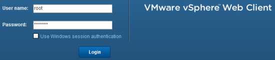
Log on to the ESX as the root user in VMware vSphere Web Client.
-
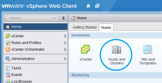
On the vSphere
Home tab, select
Hosts and Clusters.
-
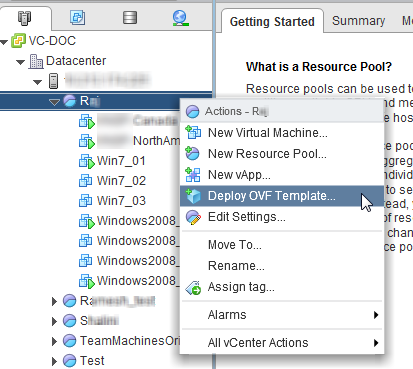
Navigate to the required node such as a resource pool, right-click, and select
Deploy OVF Template.
-
Click
Browse and locate the .ova file.
.png)
-
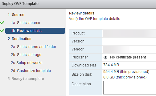
Review the details and click
Next.
-
In the
Name field, enter a name for the Sensor and select the corresponding datacenter.
Preferably, enter the same name that you entered when adding the Sensor in the Manager.
.png)
-
From the
Select virtual disk format list, select
Thin Provision.
.png)
-
In the
Setup networks section, select the switch port groups for the corresponding Sensor ports.
- For example, in scenario 2, assign vIPS Client Port for monitoring port 1 and vIPS Server Port for monitoring port 2.
- Assign temporary, non-functional switch port groups to the unused Sensor ports, that is the response port and ports 3 and 4 (for scenario 2). You select a functional switch port group for the response port when you configure the Virtual Sensor for IDS (SPAN).
Important
You should never assign the same port group to peer monitoring ports. For example, monitoring ports 3 and 4 must not be assigned the same port group. If you do, it results in a loop within the ESX.
- For the management port, assign the port group belonging to the vSwitch that you created for the Sensor management port. This switch port group must enable communication with the Manager server.
Important
Within the same Virtual Sensor, no Source (monitoring port or the response port) should have the same Destination (switch port group) as that of the Sensor management port.
.png)
-
In the
Customize template page, specify the Sensor setup details.
.png)
- Enter the same Sensor name that you specified in the Manager.
-
Optionally, enter the IPv4 address for the Sensor.
You can specify IPv4, IPv6, or both type of IP addresses to the Sensor.
- If you had specified an IPv4 address, specify the subnet mask for the IPv4 address that you provided.
-
If you had specified an IPv4 address, specify the default gateway for the IPv4 address.
This is mandatory if the Sensor needs to communicate outside its network. For example, the Manager could be on a different subnet.
- Optionally, specify an IPv6 address to the Sensor.
- If you had specified an IPv6 address, specify the default gateway for the IPv6 address.
- Specify the IPv4 or IPv6 address of the hypervisor, such as VMware ESX server on which you are deploying the Virtual Sensor.
-
Specify the Manager's primary IPv4 or IPv6 address.
To specify the Manager's secondary IP address, use the set manager secondary ip command in the Sensor CLI after the Sensor is installed.
- Specify the shared secret key and also confirm it by re-entering.
- Click Next.
-
Review the configuration that you specified, select
Power on after deployment, and then click
Finish.
Click Back and make changes, if required. Note that the Sensor setup details that you entered are listed under Properties.
.png)
-
After the Virtual Sensor is installed, open an SSH client session to logon to the Sensor.
Alternatively, you can click Launch Console in the vSphere Web Client.
.png)
- In the Sensor CLI, enter admin and admin123 as the login name and password respectively.
-
Use the
status CLI command to check if trust is established with the Manager and if signature set is present in the Sensor.
If the signature set is not present, you can deploy the signature set from the Deploy Pending Changes page of the Manager.