This section explains about the scenarios for stacked NS9500 Sensors.
Scenario 1: Node failure
Note
The examples in this section uses 4 node stack with 100 Gbps capacity. The scenarios are also valid for 2 node stack with 40 Gbps or 60 Gbps capacity.
In the event of a single or multiple node failure in a stack, the remaining Sensors continue to scan traffic and a fault is generated in the System Faults page in the Manager. You can view the status of the nodes in the stack in the Device Manager page.
Example 1: Single node failure
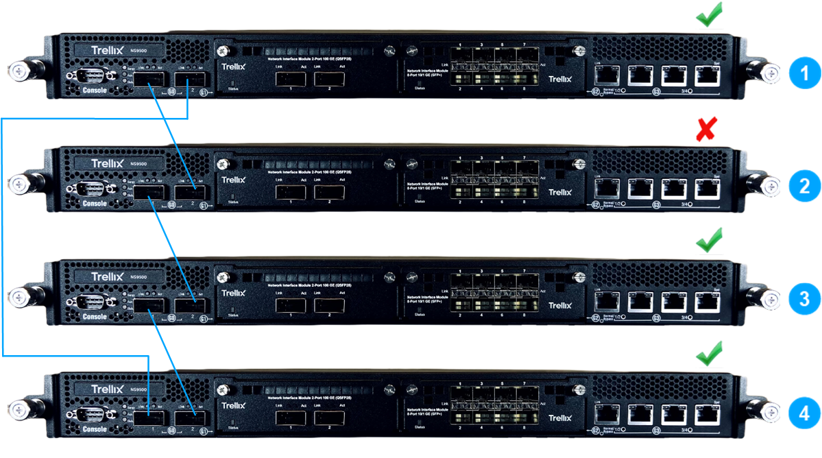
In this scenario, Node 2 in the stack becomes unresponsive. The remaining Sensors will continue to process traffic at a reduced throughput of 75 Gbps. Monitoring ports connected to the failed sensor will also experience failure. Trellix recommends you to use an Active Fail Open kit in such a scenario.
Example 2: Multiple node failure
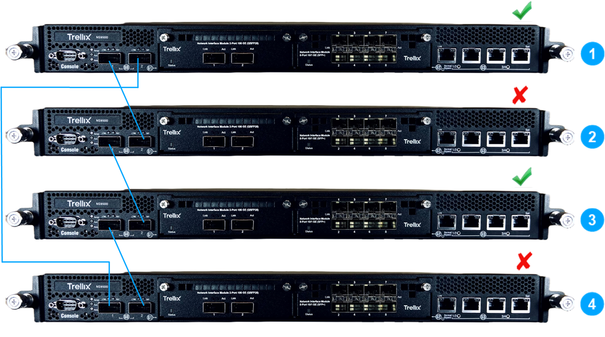
In this scenario, nodes 2 and 4 in the stack becomes unresponsive. The remaining Sensors (node 1 and 3) will function as given below:
If node 1 and node 3 are connected to the server, both nodes will continue to process traffic at 25 Gbps throughput as standalone Sensors.
If only node 3 is connected to the server, node 3 will continue to process traffic at 25 Gbps throughput. Node 1 will be active but will not process traffic.
Scenario 2: Node failure in a stack with failover
For stacked Sensor failover, heartbeat information is exchanged between the active and standby stack. This information contains the current capacity of both stacks. The traffic is processed by the stack that has the higher capacity. In the event of a node failure in the active stack, current capacity of the active stack will be less than the standby stack. In this case, the monitoring ports of the active stack will be deactivated and the traffic flows to the standby stack.
Example 1: Single node failure in active stack
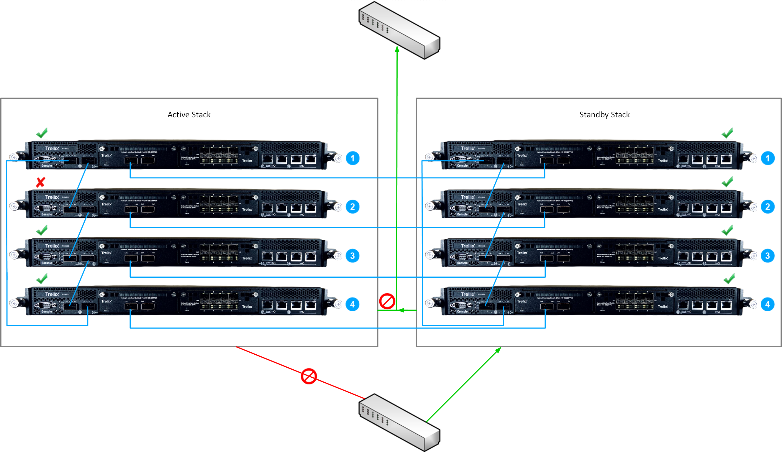
In this scenario, the workflow is as follows:
Node 2 in the active stack is not functional.
During the exchange of heartbeat information, the capacity of the active stack is lower than the standby stack.
When the active stack processes this information, the monitoring ports in the active stack is deactivated.
The standby stack takes over traffic inspection from the active stack.
Example 2: Single node failure in active and standby stacks
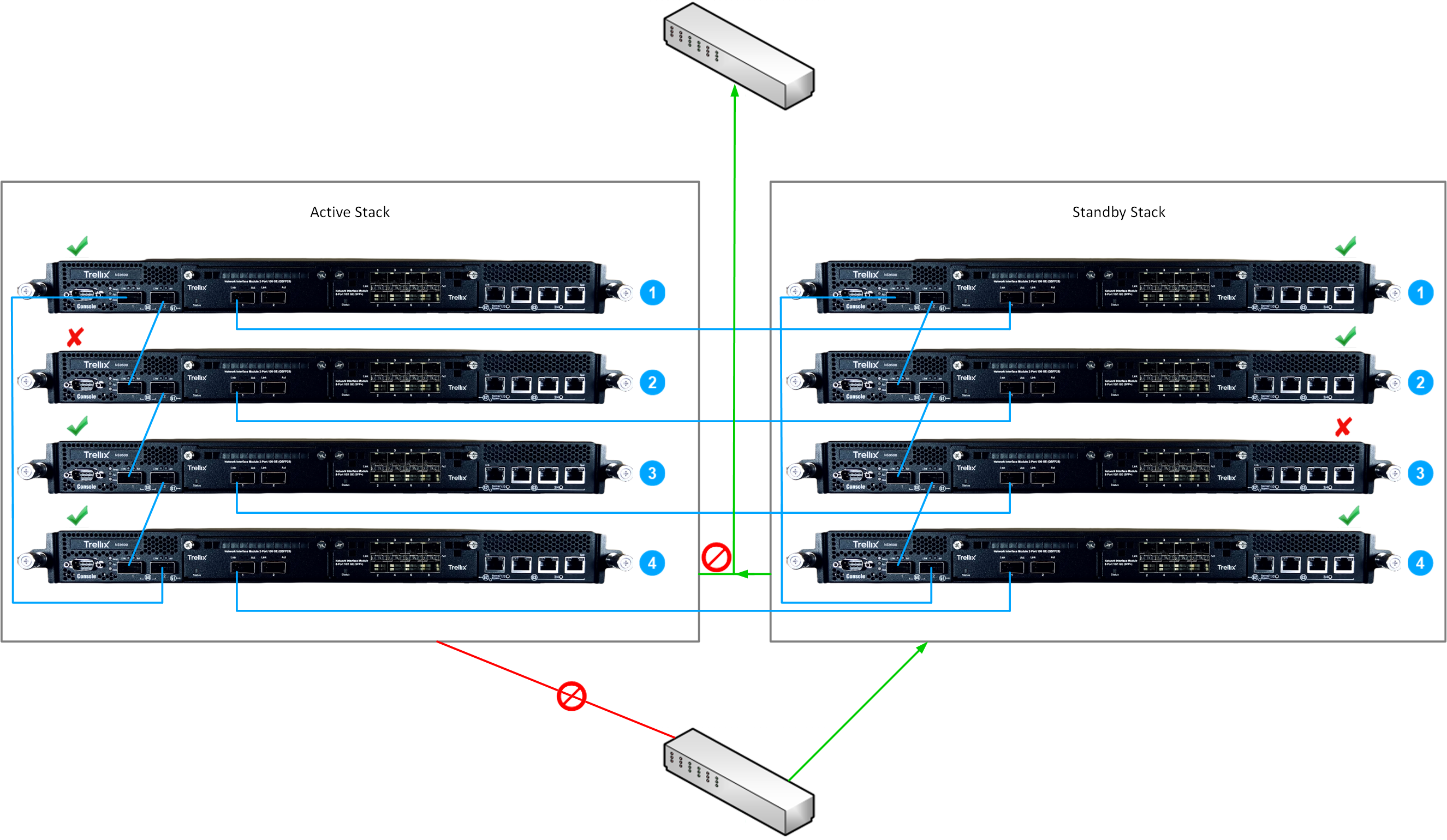
In this scenario, the workflow is as follows:
Node 2 in the active becomes unresponsive.
During the heartbeat exchange between the stacks, the capacity of the of the active stack is lower that the standby stack.
The monitoring ports on the active stack is deactivated.
The standby stack starts processing the traffic.
Node 3 in the standby stack becomes unresponsive.
During the heartbeat exchange between the stacks, the capacity of the of the active stack is equal to the standby stack.
The standby stack continues to process the traffic.
Note
Switch over occurs only when the current capacity of standby stack is lower than the active stack.