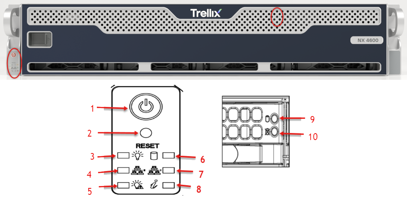
1. Power button | The main power switch applies or removes primary power from the power supply to the server but maintains standby power. Unplug the appliance before servicing. | |
2. Reset Button | Reboots the system. | |
3. Power LED | Steady on | Power on |
Blinking at 4 Hz | Checking BIOS/BMC integrity | |
Blinking at 4Hz and "i" LED is blue | BIOS firmware updating | |
Two blinks at 4 Hz, one pause 2 Hz and "i" LED blue | BMC firmware updating | |
Blinking at 1 Hz and "i" LED red | Fault detected | |
4. LAN 1 LED | Indicates network activity on a GLAN1 when flashing. | |
5. Power Failure LED | Indicates a power supply module has failed. | |
6. HDD Activity LED | Indicates activity on the hard drive when flashing. | |
7. LAN 2 LED | Indicates network activity on a LAN when flashing. | |
8. Information LED | Alerts operator to several states: | |
Red, solid | An overheat condition has occurred | |
Red, blinking at 1 Hz | Fan failure, check for an inoperative fan | |
Red, blinking at 0.25 Hz | Power failure, check for a non-operational power supply | |
Red, solid, with Power LED blinking green | Fault detected | |
Blue and red, blinking at 10 Hz | Recovery mode | |
Blue, solid | UID has been activated locally to locate the server in a rack environment | |
Blue, blinking at 1 Hz | UID has been activated using the BMC to locate the server in a rack environment | |
Blue, blinking at 2 Hz | BMC is resetting | |
Blue, blinking at 4 Hz | BMC is setting factory defaults | |
Blue, blinking at 10 Hz with Power LED blinking green | BMC/BIOS firmware is updating | |
9. Drive Device LED | Each drive carrier displays two status LEDs on the front of the carrier. | |
10. Drive Device LED | Each drive carrier displays two status LEDs on the front of the carrier. | |
Drive Carrier LED Indicators
The chassis includes externally accessible SAS/SATA drives.
Each drive carrier displays two status LEDs on the front of the carrier.
Green: When illuminated, this LED indicates drive activity. It blinks on and off when that particular drive is being accessed This function is controlled by the backplane.
Red: When illuminated, this LED indicates a drive failure. You should be notified by your system management software.
Chassis
.PNG "X12SPW_Chassis.png")
Disk Drive Carrier: Each carrier can house a hot-swappable disk drive. A drive slot map displays the disk slot numbers on top of the appliance.
Handle Release: Press this tab to release the handle. Use the handle to pull the disk drive carrier from the chassis.