Follow these steps to make sure your setup is working as designed.
Steps:
Check the icons in the Manager beside the ports you have configured as in-line fail-open passive.
They must show Up.
Check the Bypass LED on the Sensor.
LED status
Description
ON
The Sensor is in inline fail-open, inline fail-closed, SPAN, or TAP mode.
OFF
The Sensor is in bypass mode.
Check the PWR LEDs on the chassis.
Depending on which power source you use, you will see that PWR LED glowing.
Check the port status and operating mode status of the GE in-line fail-open ports.
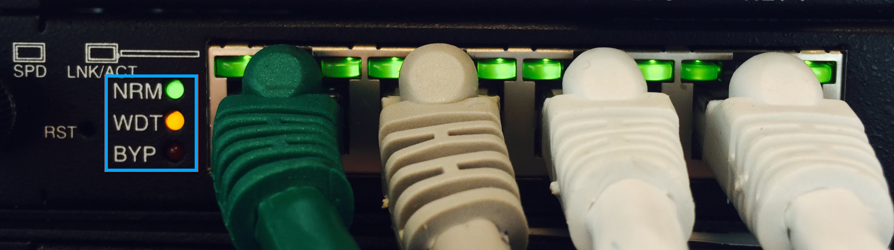
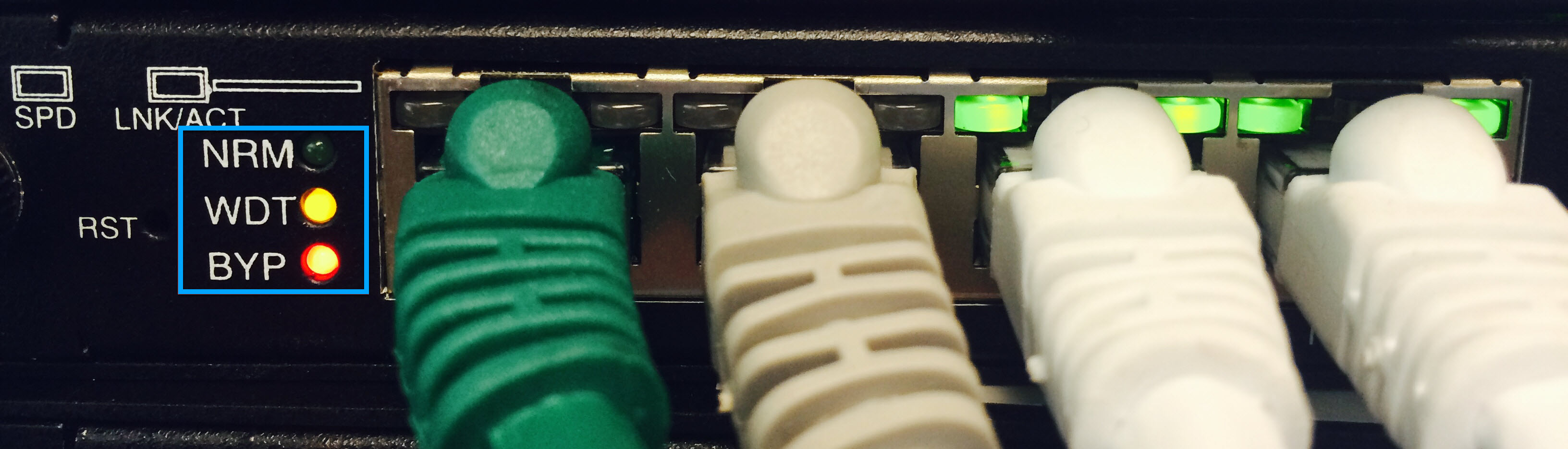
The picture below (to the left) shows you the fail-open switch in normal mode when the Sensor ports are operating normally. When the Sensor ports have gone down, the fail-open switch is seen in bypass mode as depicted the picture below (to the right).
Item
Description
NRM
Glows green when the Sensor is in normal mode of operation
WDT
Indicates watchdog timer. The Watch Dog Timer LED always blinks amber, whether the fail-open switch is in normal or bypass mode.
The blink indicates that the heartbeat pulse is being sent through the fail-open connection. The watchdog timer is always blinking, even when the fail-open switch is bypassing the Sensor because it is always sending and listening for the correct heartbeat state from the Sensor monitoring ports.
BYP
Glows red when the fail-open switch is in a bypass mode of operation