Before you begin
Before you deploy monitoring ports in inline fail-open mode, make sure the Sensor is functioning as expected with the same ports in inline fail-closed mode.
If a Virtual Sensor receives traffic from a physical network device, you can deploy an inline pair in inline fail-open mode. Consider a scenario, wherein the Virtual Sensor inspects traffic between virtual machines as shown below (scenario 4).
.png)
The monitoring port pair 1-2 is inline between physical switches 1 and 2. By default, inline monitoring ports of a Virtual Sensor are in the fail-closed mode. The network between the client and the server is broken under any of the following conditions:
- Link failure in either port 1 or 2
- Power or application failure in the Virtual Sensor
- Either vSwitch0 or vSwitch1 is down
- Link failure in either vmnic0 or vmnic1
- The ESX server is down
To mitigate the risk of network breakdown due to these conditions, you can deploy the monitoring port 1-2 in fail-open mode. Fail-open operation for the monitoring ports of a Virtual Sensor, require the use of an external copper bypass switch.
- Only Trellix-certified 10/100/1000 external Copper active fail-open bypass kits are supported.
- Installing the active fail-open bypass kit involves a brief network downtime.
.png)
Task
-
Install the 10/100/1000 external Copper active fail-open bypass kit and power it on (with dual power sources).
Refer to 1/10 Gigabit Modular Active Fail-Open Bypass Kit Guide for more information.
- Disconnect the trunk port of Physical switch 1 from vmnic0, and connect the trunk port to the port marked NET0 in the bypass kit.
- Similarly, disconnect the trunk port of Physical switch 2 from vmnic1, and connect the trunk port to the port marked NET1 in the bypass kit.
- Connect the port marked MON0 to vmnic0 and the port marked MON1 to vmnic1.
-
In the Manager, set the port in inline fail-open active mode.
- Click the Devices tab.
- Select the domain from the Domain drop-down list.
- In the left pane, click the Devices tab.
- Select the device from the Device drop-down list.
- Select Setup → Physical Ports.
- Double-click on the required port and select Inline Fail Open – Active in the Mode field.
-
Confirm and then click
Save.
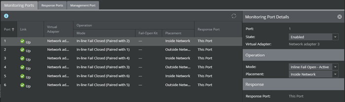
- In the Sensor CLI, run the show intfport <port number> command and verify that Fail-Open Switch shows PRESENT and Fail-Open Port shows INLINE.
- When the Sensor is operating, the switch is
on and routes all traffic directly through the Virtual Sensor.
Routing when Sensor is operating .png)
- When the Sensor fails, the switch automatically shifts the Virtual Sensor to a bypass state; in-line traffic continues to flow through the network link, but is no longer routed through the Sensor.
Routing when Sensor fails .png)
- When a monitoring port goes down, its status in the Manager is shown as unknown. A critical-fault message is also generated. This message is cleared when the monitoring port pair is back inline.
- If the monitoring port is down or if the Sensor goes into layer 2 bypass mode, the fail-open bypass kit turns on and the traffic bypasses the Sensor. If you run the show intfport <port number> command, the Fail-Open Port field displays BYPASS.
- If the Sensor layer 2 bypass mode, the Fail-Open Port field, displays LAYER2_BYPASS.
- Once the Sensor resumes normal operation, the bypass switch returns to the off state, enabling in-line monitoring again.
Note
For the details of how the external Copper active fail-open bypass kit works, see the 1/10 Gigabit Modular Active Fail-Open Bypass Kit Guide.
-
You can also configure the bypass switch to operate in tap mode.
- See 1/10 Gigabit Modular Active Fail-Open Bypass Kit Guide for information.
- There is no specific configuration in the Physical Ports page in the Manager for tap mode. The configuration is only in the bypass switch.
- When the bypass switch is in tap mode, and you run show intfport <port number> command, the Fail-Open Port field displays TAP.