As a good practice, assess the vSwitches and the switch port groups that you would require. Then you can create them in the ESX before you begin installing the Virtual Sensor. You can also create the dummy switch port groups for the ports that you do not plan to deploy.
The first two network adapters correspond to the management port and the response port respectively. The remaining adapters correspond to the monitoring ports. The following figure shows the mapping between network adapters and the Sensor ports for IPS-VM600.
.png)
The left side is the Virtual Machine Properties dialog that you can access in the vSphere client for a Virtual Sensor. To access the Virtual Machine Properties dialog, select the Virtual Sensor in the vSphere client and then select Edit virtual machine settings. The right side of the figure shows the Physical Ports page in the Manager for a Virtual Sensor.
In case of IPS-VM600, network adapters 3 through 8 correspond to the monitoring ports in the same order. Network adapters 1 and 2 correspond to the management port and the response port respectively.
Task
-
Log on to the ESX as the root user in VMware vSphere Web Client.
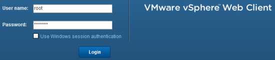
-
On the vSphere
Home tab, select
Hosts and Clusters.
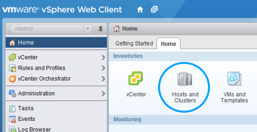
-
Under the corresponding ESX, select the required Virtual Sensor.
You can view the network adapters corresponding to the Sensor ports in the VM Hardware section. The current status of these adapters is also displayed.
.png)
- Click Edit Settings in the VM Hardware section.
-
In the
Edit Settings dialog, select
Connected check box for the required network adapters (Sensor ports) and click
OK.
.png)
In the VM Hardware section, you can verify that these network adapters are now connected.