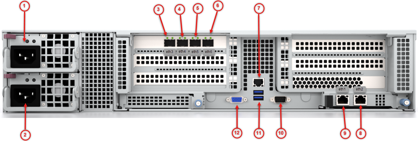
1) Power Supply 1 | 7) IPMI Port |
2) Power Supply 2 | 8) ether2 (RJ45) Submission/Cluster Communication 2 Port |
3) ether3 (SFP+) Submission/Cluster Communication 3 Port | 9) ether1 (RJ45) Management 1 Port |
4) ether4 (SFP+) Submission/Cluster Communication 4 Port | 10) Serial Console Port |
5) ether5 (SFP+) Unsupported | 11) USB 3.1 Port |
6) ether6 (SFP+) Unsupported | 12) VGA Connector |
Power
Power: Connect your power source to this port to provide power to the appliance. The appliance comes with one redundant power supply unit for use if the primary unit fails.
I/O Ports
Serial Console: Connect to this port to manage the appliance from your terminal.
Video: Connect a monitor to this port to view the appliance's command-line interface.
USB 3.1: These ports are USB 3.1 compliant.
Management Ports
ether1 (RJ45): Connect your LAN to this port to enable remote access to the CLI and Web UI. The RJ45 connector is a 100/100/10GBASE-T port.
IPMI: Connect for access to out-of-band management functions, including power control, console redirection, and appliance health status. The connector is a 10/100/1000BASE-T port.
Submission/ Cluster Ports
ether2 through ether4: Use these ports as an optional dedicated interface for communication with sensors or other MVX cluster components. The ether2 connector is a 100/1000/10GBASE-T port. The ether3–ether4 connectors are SFP+ connectors and they support 1G or 10Gbps data rate, use one of the following 10GbaseCu (5m direct attach cable), 1GbaseT (SFP), 1GbaseSX/10GbaseSR (dual rate SFP+), or 1GbaseLX/10Gbase LR (dual rate SFP+). See the chapter “Performing the Initial Configuration” in the MVX Deployment Guide for your software release for more information.