CHAPTER 1: The FireEye VX 5500
The FireEye VX 5500 appliance is a powerful stand-alone analysis engine that integrates with FireEye sensors to provide a flexible, scalable, and geographically expansive security solution.
For information about integrating the VX Series appliance with NX Series sensors and CM Series appliances, see the Network Security Deployment Guide for your software release.
The Front View
The VX 5500 comes with a sleek removable bezel that can be removed to access the chassis.
Bezel

1) Bezel Release | 4) ether2 LED |
2) Universal Information LED | 5) Device Activity LED |
3) ether1 LED | 6) Power LED |
Bezel Release: Slide the release tab to the right to remove the bezel from the appliance to access the chassis.
LEDs
The front panel has LEDs that provide critical information about parts of the appliance. The following table describes each LED.
VX 5500
CHAPTER 1: The FireEye VX 5500
LED | Flashing | Steady | Off | Normal State |
|---|---|---|---|---|
Universal Information | Flashing once per second and red indicates fan failure. | Solid and red indicates an overheat condition, which may be cause by cables obstructing the airflow in the appliance or the ambient room temperature being too high. | Operating normally | Off |
ether1 | Network activity via ether1 port | N/A | No activity | Flashing |
ether2 | Network activity via ether2 port | N/A | No activity | Flashing |
Device Activity | Operating normally | N/A | No activity | Flashing |
Power | N/A | Operating normally | Not drawing power | Steady |
Chassis

1) Disk Drive Carrier | 3) Reset Button |
2) Unit Identifier Button | 4) Power Button |
Disk Drive Carrier: Each carrier can house a hot-swappable disk drive.
Hardware Administration GuideThe Rear View
Buttons
The chassis has one reset button, one power button, and one UID button. Use them to perform basic operations of the appliance.
Unit Identifier Button: Pressing this button illuminates an LED on both the front and rear of the chassis for easy system location. The LEDs remain on until the button is pressed a second time.
Reset Button: Use the reset button to restart the appliance.
Power Button: Use the power button to turn the appliance on or off. Turning off the power with this button removes the main power but keeps the standby power supplied to the appliance. Therefore, unplug the appliance before servicing.
The Rear View

1) Power Port | 6) ether1 (RJ45) Management 1 Port |
2) Serial Console Port | 7) ether2 (RJ45) Submission/Cluster Communication 2 Port |
3) IPMI/Serial over Ethernet Port | 8) ether3 (RJ45) Submission/Cluster Communication 3 Port |
4) USB 2.0 Ports | 9) ether4 (RJ45) Submission/Cluster Communication 4 Port |
5) USB 3.0 Ports | 10) Video Port |
Power Port
Power: Connect your power source to this port to provide power to the appliance. The appliance comes with one redundant power supply unit for use if the primary unit fails. See Removing and Replacing a VX 5500 Power Supply Unit on page 29 for more information.
I/O Ports
Video: Connect a monitor to this port to view the appliance's command-line interface.
USB 2.0: These ports are USB 2.0 compliant.
© 2017 FireEye
USB 3.0: These ports are USB 3.0 compliant.
Serial Console: Connect to this port to manage the appliance from your terminal.
Management Ports
ether (RJ45): Connect your CM-facing switch to this port to manage the appliance. The RJ45 connector is a 10/100/1000BASE-T port.
IPMI: Connect for access to out-of-band management functions, including power control, console redirection, and appliance health status. The connector is a 100BASE-T port.
Submission/Cluster Ports
ether (RJ45): Use this port as an optional dedicated interface for communication with sensors or other MVX cluster components. The connector is a 10/100/1000BASE-T port. See the chapter “Performing the Initial Configuration” in the Network Security Deployment Guide for your software release for more information.
Hardware Administration Guide VX Series Deployment
CHAPTER 2: Deployment
This chapter describes how to deploy the VX 5500 appliance in your network.
VX Series Deployment
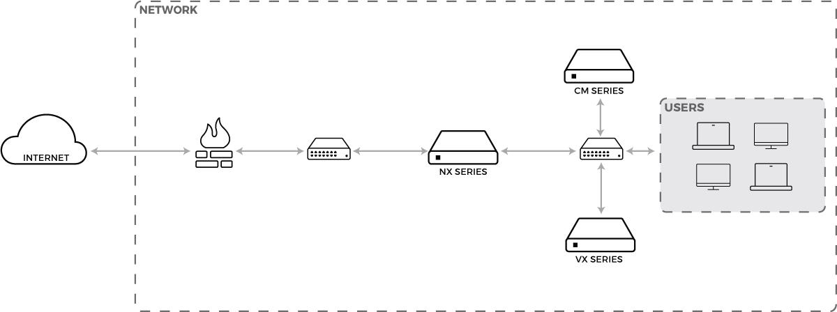
The VX Series appliance acts as a compute node that analyzes submissions received by NX Series sensors. In order for NX Series sensors and VX Series appliances to communicate, they must belong to the same MVX cluster and be managed by the same CM Series platform. The following figure shows how to connect your VX 5500 to your CM Series platform in a typical network topology.

All VX Series appliances in a cluster must be within the same physical location. They can be remotely located from the managing CM Series platform and the sensors in its Threat Management Platform. For information about additional deployments and setting up MVX clusters, see the Threat Management Platform Deployment Guide for your software release.
© 2017 FireEye
9
VX 5500
CHAPTER 2: Deployment
Prerequisites
Before connecting the VX 5500 appliance to your network, ensure that your CM-Series-facing switch provides 10/100/1000BASE-T Ethernet output.
Cabling
To connect your VX 5500 appliance to your network:
ether1: Connect one end of an Ethernet cable to the VX 5500 appliance’s ether1 port, and connect the other end to your CM-Series-facing switch.
This is the default management, submission, and cluster communication interface.
(For optional dedicated submission interface) ether2: Connect one end of an Ethernet cable to the VX 5500 appliance’s ether2 port, and connect the other end to your sensor-facing switch.
(For optional dedicated cluster interface) ether3 and ether4: Connect one end of an Ethernet cable to the VX 5500 appliance’s ether3 or ether4 port, and connect the other end to your cluster-facing switch.
For information about changing the default submission and cluster interfaces, see the chapter “Performing the Initial Configuration” in the Threat Management Platform Deployment Guide for your software release.
10
© 2017 FireEye
Hardware Administration Guide
Before You Begin
CHAPTER 3: Installation
This chapter provides information about the site requirements of your installation location.
Before You Begin
Follow the steps in this section before you install the appliance.
Before Opening the Box
Review the Packing Slip contained in the plastic slip attached to the top of the box. Ensure the shipment contains the correct appliance.
Ensure the serial number listed on the Packing Slip matches the one specified on the sticker located on one side of the box.
If there appears to be damage to the box, file a damage claim with the carrier who delivered it.
Unpacking the Appliance
Carefully remove the appliance from the box in an area away from heat, electrical noise, and electromagnetic fields.
Ensure your box contains:
The correct appliance model
One set of rails
An accessory kit
The accessory kit contains:
(8) 10-32 cage nuts
(8) 10-32 Phillips screws
8 washers
Safety Guide
© 2017 FireEye 11
VX 5500CHAPTER 3: Installation
Online Documents Portal Referral
The cables listed in Cabling Requirements on the facing page.
Tools You'll Need
Phillips crosshead screwdriver
ESD wrist strap
Site Requirements
This section contains guidelines for the appropriate location of your rack unit and appliance and precautions.
Installation Site Guidelines
Follow these guidelines when you select an installation site:
Leave enough clearance in front of the rack for its door to open completely without obstruction.
Avoid environments that produce heat, electrical noise, and electromagnetic fields.
Only install the appliance in a Restricted Access Location such as a service closet or dedicated equipment room.
Make sure the location is properly ventilated.
Make sure there is sufficient space for air flow.
Rack Precautions
FireEye recommends that you mount the appliance in a standard 19-inch rack. The vertical hole spacing on the rack rails must meet standard ANSI/EIA-310-C requirements, which call for a one-inch (2.54-cm) spacing.
Consider the following before installing your appliance in the rack:
Ensure the leveling jacks on the bottom of the rack are fully extended to the floor with the full weight of the rack resting on them.
In a single-rack installation, stabilizers should be attached to the rack.
In a multiple-rack installation, the racks should be coupled together to increase their stability.
Always make sure the rack is stable before extending a component from the rack.
Only extend one component from the rack at a time--extending two or more simultaneously may cause the rack to become unstable.
Ensure your rack meets the safety requirements of UL 60950-1.
Hardware Administration Guide Site Requirements
Server Precautions
FireEye recommends reviewing the electrical and general safety precautions that came with each component you intend to install in the rack.
Review the following before installing the appliance in the rack:
Determine the placement of each component in the rack.
Ensure there is a minimum clearance of six inches behind the chassis to allow for easy cable management.
Install the heaviest component at the bottom of the rack first, then move up.
Allow hot-swappable power supply units and disk drives to cool before handling them.
Use a regulating uninterruptible power supply to protect your components from voltage spikes, power surges, and failure during a power outage.
Keep all of the rack's doors and panels closed when you are not servicing the components.
Rack-Mounting Precautions
Consider the following safety precautions when you install the appliance in the rack:
Make sure the appliance is grounded at all times to prevent damage from electrostatic discharge.
Use an electrostatic wrist guard when handling the appliance.
At least two technicians should be involved to install the appliance safely.
FireEye recommends only individuals with rack-mounting experience should install the appliance.
Install the appliance in an environment compatible with the manufacturer's maximum rated ambient temperature (Tmra) for each component in your rack.
Ventilation Requirements
Ventilation and optimal location are essential to the proper operation of the VX Series appliance. Give the unit at least six inches of space around ventilation openings so that adequate ventilation is possible.
Cabling Requirements
The VX 5500 ships with the following cables:
(2) 6 ft AC power cord, SVT, 60°C, 3x18AWG (0.824mm²)
(1) 6 ft null modem DB9 female serial cable
© 2017 FireEye
VX 5500
CHAPTER 3: Installation
You must provide any additional cables required to connect your system to the network and other devices. Do not exceed the maximum run length of the additional cables you provide.
Power Requirements
The VX 5500 uses a 750 W power supply unit with an input rating of 100-240 VAC (±10%), 8-4.5 A at 50-60 Hz.
Ensure your power source has sufficient electrical overload protection. In North America, connect the rack to a power source with over-current protection that complies with UL 489. In Europe, the over-current protection must comply with IEC standards.
Rack Installation
This section explains how to install your appliance in a standard 19-inch wide rack with the equipment provided. Because various rack units are available, the assembly procedure may differ slightly from the following instructions. Refer to the installation instructions that came with your rack.
Installing the Outer Rails on the Rack
Attach a short bracket to the front side of the right outer rail and a long bracket to the rear side of the right outer rail.
Adjust the length of the right outer rail to the size of the rack.
Attach the right outer rail to the right side of the rack using the screws provided.
Repeats steps 1-3 with the left outer rail.
Mounting the Appliance on the Rack
Align the rear of the inner rails installed on the appliance with the front channels of the outer rails installed on the rack.
Slide the appliance about halfway into the rack.
Press the rail-release notches down on both rails and slide the appliance fully into the rack.
(Optional) Further secure the appliance to the rack by inserting screws through the ears of the appliance and fastening them to the rack.
Attaching Cables to your Appliance
Connect the VX 5500 to one or more network devices using the appropriate cables specific to the deployment of your choice.
Connect the power cables to the power ports on the back of the appliance.
14
© 2017 FireEye
Hardware Administration Guide
Rack Installation
Turning On the Appliance
Power on the appliance by pressing the power button behind the bezel.
© 2017 FireEye
15
VX 5500
CHAPTER 3: Installation
16
© 2016 FireEye
Hardware Administration GuideNetwork Information Requirements
CHAPTER 4: Baseline Configuration
This chapter contains information and instructions for performing the basic configuration of your appliance.
Network Information Requirements
Network Item | Information Needed |
|---|---|
FireEye Appliance |
|
Domain Name Service (DNS) | IP address of one or more DNS servers |
Network Time Protocol (NTP) Service (Optional) | IP address of one or more NTP servers |
Remote Management (Optional) | If you want to access the appliance's CLI remotely, the remote system must have an SSH client. |
CMS (Central Management System) (Optional) |
|
Required Ports and Protocols
The table below outlines the main connections for the VX 5500 appliance’s communications. Open the ports listed below on your firewall to permit these connections.
© 2017 FireEye17
Source | Destination | Destination Port | User Configurable | Notes |
|---|---|---|---|---|
VX 5500: Ether1* | cloud.fireeye.com | TCP 443 | Yes | Dynamic Threat Intelligence (DTI) Cloud Update Service |
Administrator Workstation | VX 5500: Ether1 | TCP 22 | No | CLI Management |
VX 5500: Ether1 | SMTP Relay | TCP 25 | No | SMTP Alerts |
VX 5500: Ether1 | Internal DNS Servers | TCP/UDP 53 | No | DNS Queries |
VX 5500: Ether1 | NTP Servers | UDP 123 | No | NTP |
VX 5500: Ether1 | SIEM/Syslog Server | UDP 514 | No | Syslog |
VX 5500: Ether1 | SNMP Server | UDP 162 | No | SNMP |
CM-Managed VX 5500: Ether1** | CM Ether1 | TCP 22 | No | CM Management Connection |
Broker*** | Broker | 25672 and 4369 | No | Inter-broker communication |
Broker*** | Compute Node | 5671 | No |
Hardware Administration Guide
Required Ports and Protocols
Source | Destination | Destination Port | User Configurable | Notes |
|---|---|---|---|---|
* This is the default destination and port for stand-alone appliances and the CM Series platform. For a CM Series platform or standalone NX Series appliance running Release 7.5.0 or later, or a standalone EX Series appliance running Release 7.6.0 or later, the DTI source server can be either cloud.fireeye.com or staticcloud.fireeye.com. For a managed NX Series or EX Series appliance running these releases, the default DTI source server is the CM Series platform, but it can be either of the two servers mentioned above instead. ** For a managed appliance running Release 7.6.0 or later that uses the CM Series platform as its DTI source server, single-port communication is the default behavior. This means CM Ether1 port (TCP 22) is used for both DTI traffic and management traffic, unless otherwise configured. For details, see the CM Series Administration Guide or the System Administration Guide for your appliance. ***In a FireEye Network Security configuration. | ||||

For information about CM Series High Availability (HA) ports, see the CM Series High Availability (HA) Deployment Guide.
VX 5500 | CHAPTER 4: Baseline Configuration |
20 | © 2016 FireEye |
Hardware Administration Guide
Return Process
CHAPTER 5: Replacements
Return Process
If you believe you have a defective part, you must first contact FireEye Technical Support, who will validate whether or not the part is defective. If the part is defective, Technical Support will initiate a Return Materials Authorization (RMA). No part can be returned without a FireEye-issued RMA number.
After receiving the replacement part from FireEye, please package and return the defective part within five (5) days, at FireEye's cost (provided that you utilize FireEye's designated courier service). If you fail to return the defective part within ten (10) business days after receiving the replacement, FireEye may invoice you as detailed in our Support Terms and Conditions, described here: http://www.fireeye.com/support/terms-and-conditions.html.
In the case of a defective disk drive or a defective system with disk drives, you may retain the disk drive(s) if you have purchased the Non-Returnable Disk Drive support option. Follow these instructions:
To return a defective part or system:
Pack the defective part or the entire appliance in the packaging that the replacement part was received in, or in its original packaging material (or equivalent).
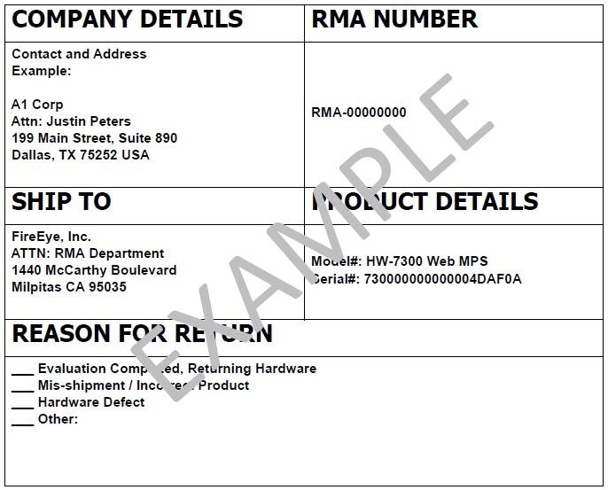
Place a copy of the associated RMA Form (example shown below) inside the package. If you have more than one package, place a copy inside each package.
Write the associated RMA number on the outside of each return package and in the reference field on each waybill. Returns cannot be processed without referencing the associated RMA number.
Do not insure the shipment. FireEye is self-insured. Please declare “$0” in the “value for carrier” section.
Send an email to RMA_Ops@fireeye.com listing the RMA number(s), the carrier name, and the carrier tracking number(s) for the return package.
If you do not have a return shipping label, contact FireEye operations at RMA_Ops@fireeye.com and they will provide one for your return.
© 2017 FireEye 21
VX 5500
CHAPTER 5: Replacements
All international shipments require three copies of a commercial invoice (CI). FireEye provides a partially completed CI. Please either use this CI, after completing the remaining required information, or create your own if you prefer. Please contact your distribution partner who can assist you. If you require additional assistance, please contact RMA_Ops@fireeye.com.
Send the package directly to the location specified in the "SHIP TO" section on the RMA Form (example shown below) provided in the replacement part package.
For questions regarding an RMA return or status, please email: RMA_Ops@fireeye.com or call +1-408-321-7798.
Enclosed with your replacement part, you will receive a FireEye RMA Form similar to the following:
Replacing an Appliance Including Disk Drives
Before replacing your VX 5500, take a backup of the current system, if possible. FireEye recommends that regular, full system backups are taken. For more information, see Backing Up and Restoring the Appliance Database on page 24. If you cannot back up the appliance, make sure your latest system backup is available. Contact FireEye Technical Support if you have questions on backing up your appliance.
To replace an appliance including the disk drives:
22
© 2017 FireEye
Replacing an Appliance Excluding Disk Drives
Before replacing an appliance, take a backup of the current system, if possible. FireEye recommends that regular, full system backups are taken. If you cannot back up the appliance, make sure your latest system backup is available. For more information, see Backing Up and Restoring the Appliance Database on the next page. Contact FireEye Technical Support if you have questions on backing up your appliance.
To replace an appliance without replacing the disk drives:
Perform an orderly shutdown of the defective appliance.
Unplug the appliance.
 Keep the power cord and cables for your replacement appliance.
Unrack the defective appliance and rack-mount and re-cable the replacement appliance.
Power on the replacement appliance.
Configure the appliance as described in “Initial Configuration” of the System Administration Guide specific to your FireEye Series appliance and software release.
Using a console connection, restore the appliance's configuration and database as described in Backing Up and Restoring the Appliance Database on the next page.
Install replacement licenses as described in Applying License Keys on page 27.
Set the DTI credentials as described in “Configuring DTI Credentials” in the System Administration Guide or Administration Guide specific to your FireEye Series appliance and software release.
VX 5500
CHAPTER 5: Replacements
Power on the replacement appliance and watch the boot up process on the connected monitor.
When a foreign configuration is detected, press F to import the saved configuration from the previous system.
Configure the appliance via the console as described in "Initial Configuration" in the System Administration Guide specific to your FireEye Series appliance and software release.
Install replacement licenses as described in Applying License Keys on page 27.
Set the DTI Credentials as described in “Configuring DTI Credentials” in the System Administration Guide or Administration Guide specific to your FireEye Series appliance and software release.
Backing Up and Restoring the Appliance Database
Before replacing your VX 5500 appliance, take a backup of the current system so you can later restore it on the replacement.
Backing Up and Restoring the Appliance Database Using Release 7.9 and Later
Backing Up the Appliance Database
Follow these steps to back up the appliance database using the CLI.
To back up the appliance database:
Enable the CLI configuration mode.
VX 5500 > enable VX 5500 # configure terminalSpecify the type of profile.
To set the profile for the configuration database, enter:
VX 5500 (config) # backup profile configTo set the profile for the FireEye appliance database, enter:
VX 5500 (config) # backup profile fedbTo set the profile for both the configuration database and the FireEye appliance database, enter:
VX 5500 (config) # backup profile config+fedbTo set the profile for the configuration database, FireEye appliance database, and detected data (malware, alerts, reports, and so on), enter:
VX 5500 (config) # backup profile full
Specify the location for the backup file.
To save the backup file to a local destination on the appliance, enter:
VX 5500 (config) # backup profile <profile> to local
24
© 2017 FireEye
To save the backup file on a remote server, enter:
vx 5500 (config) # backup profile profile to urlwhere url is the specified remote location using the following format:
scp://username:password@hostname/remote pathTo save the backup file to a USB drive on your local machine, enter:
vx 5500 (config) # backup profile profile to usb
Specify the prefix for the backup file name.
vx 5500 (config) # backup profile profile to backup_location prefix prefixYou can use the customized prefix to sort the list of the backup files.
(Optional) Monitor the progress of the backup operation.
To disable progress tracking for the backup operation, enter:
vx 5500 (config) # backup profile profile to backup_location progress no-trackTo enable progress tracking for the backup operation, enter:
vx 5500 (config) # backup profile profile to backup_location progress track
By default, progress tracking is enabled.
You can cancel progress tracking by using Ctrl+C. The backup operation still happens in the background. Use the show backup status command to find the status of the backup operation.
(Optional) Disable public and private key encryption for the backup operation.
vx 5500 (config) # backup profile profile to backup_location no-encryptionEach backup file is signed by default using the public and private key pairs. By default, encryption is always included in the backup.

Encryption delays the backup operation. Backups are encrypted only using static keys.
[IMAGE PLACEHOLDER: Circular blue icon indicating cancellation]
To cancel a backup that is in progress, enter the backup cancel command. When you cancel the backup operation that is in progress, the system finishes the current step before canceling the entire operation.
The following example backs up the configuration database, detected data, and artifacts to a local destination on the appliance:
vx 5500 (config) # backup profile full to local
Step 1 of 4: Backing up config db
100.0% [########################################]
Step 2 of 4: Backing up fedb
100.0% [########################################]
Step 3 of 4: Backing up Artifacts
100.0% [########################################]
Step 4 of 4: Generating Backup package
100.0% [########################################]© 2017 FireEye
VX 5500
CHAPTER 5: Replacements
Restoring the Appliance Database
Follow these steps to restore the appliance database from a backup file using the CLI.
To restore the appliance database from a backup file:
Enable the CLI configuration mode.
VX 5500 > enable VX 5500 # configure terminalLocate the backup FEBKP file you want to restore.
To display a list of the backup files on the USB drive, enter:
VX 5500 (config) # show backup available on-usbTo display a list of the backup files on the appliance, enter:
VX 5500 (config) # show backup available local
Specify a backup profile.
To set the profile for the configuration database, enter:
VX 5500 (config) # restore profile configTo set the profile for the FireEye appliance database, enter:
VX 5500 (config) # restore profile fedbTo set the profile for both the configuration database and the FireEye appliance database, enter:
VX 5500 (config) # restore profile config+fedbTo set the profile for the configuration database, FireEye appliance database, and detected data (malware, alerts, reports, and so on), enter:
VX 5500 (config) # restore profile full
Specify the location of the backup file.
To restore the backup from the local destination on the appliance, enter:
VX 5500 (config) # restore profile profile from localTo restore the backup from a remote server, enter:
VX 5500 (config) # restore profile profile from urlwhere url is the specified remote location using the following format:
https or scp://username:password@hostname/remote path
To restore the backup from a USB drive on your local machine, enter:
VX 5500 (config) # restore profile profile from usb
Enter the name of the backup file.
VX 5500 (config) # restore profile profile from backup location backup name(Optional) Restore the network settings from the relevant backup.
VX 5500 (config) # restore profile profile from backup location backup name include-network-config
By default, the network settings are not included in the restore operation.
 Do not restore the current network settings while the appliance is performing a restore operation from a remote server.
7. (Optional) Monitor the progress of the restore operation.
To disable progress tracking for the restore operation, enter:
vx 5500 (config) # restore profile profile from backup location backup name progress no-trackTo enable progress tracking for the restore operation, enter:
vx 5500 (config) # restore profile profile from backup location backup name progress track
By default, progress tracking is enabled.
You can cancel progress tracking by using Ctrl+C. The restore operation still happens in the background. Use the show restore status command to find the status of the restore operation.
The following example shows how to restore a configuration database backup from your local appliance:
vx 5500 (config) # restore profile config from local backup wMPS-Config-7.5.0-sulabh-wmps-20141118-133123.febkp
Step 1 of 3: Performing Sanity checks
100.0% [###############################################]
Step 2 of 3: Extracting backup package
100.0% [###############################################]
Step 3 of 3: Restoring config db
100.0% [###############################################]Applying License Keys
After you replace an appliance, you must apply replacement license keys.
To apply a license key from the CLI:
Enable the CLI configuration mode.
VX5500 > enable VX5500 # configure terminalEnter the license key.
VX 5500 (config) # license install <license-key>Repeat step 2 for each additional license key you need to apply.
Identifying the Failed Disk Drive
Before removing and replacing the failed disk drive from your appliance, you must first identify the slot in which it resides.
To identify the slot number of a failed drive from the CLI:
Enable configuration mode.
VX 5500 > enable VX 5500 # configure terminal
© 2017 FireEye
27
VX 5500CHAPTER 5: Replacements
Enter the show media disk command.
Note the slot number of the failed drive. View the sample output below for reference.
Enclosure Device ID: 12
Slot Number: 16
Drive's position: DiskGroup: 0, Span: 0, Arm: 0Enclosure position: 1
.
.
.
Physical Sector Size: 0
Firmware state: Failed
Commissioned Spare : No
.
.
.
Proceed to the following section for instructions on removing and replacing the disk drive within the specified slot number.
Removing and Replacing a VX 5500 Disk Drive
Perform the following steps to remove and replace a disk drive:
Slide the bezel release tab to the right to unlatch it from the chassis.
Gently remove the bezel from the appliance to reveal the disk drives.
Locate the disk drive carrier that contains the failed disk drive.
Push the maroon button to release the latch handle.
Carefully pull the latch handle forward.
Pull the handle to slide the disk drive from its slot.
Use the latch handle on the new drive carrier to slide the new drive into the empty slot. When the drive is fully inserted into the slot, push the latch handle in until it clicks.
To verify the RAID functionality of the replacement drive:
Enable configuration mode.
VX 5500 > enable VX 5500 # configure terminalEnter the show system hardware status raid command.
Verify that the disk status of the replaced drive is “Online.”
Hardware Administration Guide
Removing and Replacing a VX 5500 Power Supply Unit
Removing and Replacing a VX 5500 Power Supply Unit
Perform the following steps to remove and replace a power supply unit (PSU):
At the rear of the appliance, remove the power cable from the failed PSU.
Press the release lever toward the handle in a pinching gesture to unlatch the unit and, while continuing to squeeze, pull out the PSU.
Insert the replacement PSU in the slot and slide it in until it clicks into place.
© 2017 FireEye
29
VX 5500
CHAPTER 5: Replacements
30
© 2016 FireEye
Hardware Administration GuideAppendix 1: System Specifications
Appendices
Appendix 1: System Specifications
The table below provides the technical specifications of the FireEye VX 5500.
Component | VX 5500 Specifications |
|---|---|
Form Factor | 1U Rack-Mount |
Weight of Packaged Appliance | 39 lbs (17.7 kg) |
Dimensions (W x D x H) | 17.2 x 25.6 x 1.7 inches (437 x 650 x 43.2 mm) |
Enclosure | 1 RU, Fits 19-inch Rack |
Management Interfaces | (1) 10/100/1000BASE-T Ports |
Submission Interfaces | (3) 10/100/1000BASE-T Ports |
Drive Capacity | (2) 2 TB HDD, RAID 1, 3.5 inch, FRU |
AC Power Supply | Redundant (1+1), FRU, 750 W @ 100-240 VAC (±10%) 8-4.5 A, 50/60 Hz IEC60320-C14 inlet |
Maximum Power Consumption | 185 W |
Operating Temperature | 10° to 35° C |
Maximum Thermal Dissipation | 632 BTU/hour |
Appendix 2: Product Compliance Information
The following table lists the electromagnetic compatibility (EMC), low voltage directive (LVD), safety, and other regulatory standards met by the FireEye VX Series appliances.
VX | EMC | LVD/Safety | Environment |
|---|---|---|---|
5500 | FCC (Part 15 Class-A), CE (Class-A), CNS 13438, | IEC / EN / CSA 60950* | RoHS |
*All current amendments